Lab Home page
 |
Polska wersja |
|
Lab Home page |
Department of Microelectronic Systems, Faculty of Electronics, Telecommunications and Informatics, Gdansk University of Technology |
|
AT keyboard has DIN connector with the following 4 signals:
CLOCK, DATA, +5V and GND. Power supply +5V
is generated by PC, ground GND is also connected to computer's ground.
Signals CLOCK and DATA are of "open collector" type.
Keyboard and computer both have resistors pulling up
CLOCK and DATA to power supply +5V.
Data transmission between computer and keyboard is done using bidirectional serial
protocol - data are read bit by bit with each clock cycle.
Keyboard can send data to PC and PC can also send data to keyboard, but
the PC has always a priority and can stop the transmission any time by
setting CLOCK low.
Data sent by keyboard to PC are read during falling edge of the clock.
Data sent by PC are always read on rising edge of the clock.
Despite the transmission direction, clock is always generated by the keyboard.
If PC wants to transmit data, it has to "ask" the keyboard for generating
the clock signal:
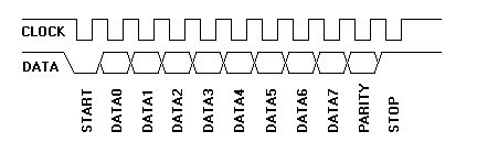
The delay from the rising edge of the clock CLOCK to a change of signal DATA is at least 5us. The delay from change of DATA to falling edge of the clock CLOCK is at least 5us and at most 25us. After sending stop bit, the keyboard waits for at least 50us, until it transmits next data. Codes generated by the keyboard are presented in the table below. "Make" code is sent after pressing a key. If the key is kept pressed down, after "typematic delay" keyboard starts periodically sending "make" codes with frequency "typematic rate". If the key is released, the keyboard generates "break" code.
| default value | acceptable range | |
| typematic delay [s] | 0.5 | 0.25 - 1 |
| typematic rate [cps] (cps = character per second) |
10.9 | 2 - 30 |
|
KEY |
MAKE |
BREAK |
----- |
KEY |
MAKE |
BREAK |
----- |
KEY |
MAKE |
BREAK |
|
A |
1C |
F0,1C |
|
9 |
46 |
F0,46 |
|
[ |
54 |
FO,54 |
|
B |
32 |
F0,32 |
|
` |
0E |
F0,0E |
|
INSERT |
E0,70 |
E0,F0,70 |
|
C |
21 |
F0,21 |
|
- |
4E |
F0,4E |
|
HOME |
E0,6C |
E0,F0,6C |
|
D |
23 |
F0,23 |
|
= |
55 |
FO,55 |
|
PG UP |
E0,7D |
E0,F0,7D |
|
E |
24 |
F0,24 |
|
\ |
5D |
F0,5D |
|
DELETE |
E0,71 |
E0,F0,71 |
|
F |
2B |
F0,2B |
|
BKSP |
66 |
F0,66 |
|
END |
E0,69 |
E0,F0,69 |
|
G |
34 |
F0,34 |
|
SPACE |
29 |
F0,29 |
|
PG DN |
E0,7A |
E0,F0,7A |
|
H |
33 |
F0,33 |
|
TAB |
0D |
F0,0D |
|
U ARROW |
E0,75 |
E0,F0,75 |
|
I |
43 |
F0,43 |
|
CAPS |
58 |
F0,58 |
|
L ARROW |
E0,6B |
E0,F0,6B |
|
J |
3B |
F0,3B |
|
L SHFT |
12 |
FO,12 |
|
D ARROW |
E0,72 |
E0,F0,72 |
|
K |
42 |
F0,42 |
|
L CTRL |
14 |
FO,14 |
|
R ARROW |
E0,74 |
E0,F0,74 |
|
L |
4B |
F0,4B |
|
L GUI |
E0,1F |
E0,F0,1F |
|
NUM |
77 |
F0,77 |
|
M |
3A |
F0,3A |
|
L ALT |
11 |
F0,11 |
|
KP / |
E0,4A |
E0,F0,4A |
|
N |
31 |
F0,31 |
|
R SHFT |
59 |
F0,59 |
|
KP * |
7C |
F0,7C |
|
O |
44 |
F0,44 |
|
R CTRL |
E0,14 |
E0,F0,14 |
|
KP - |
7B |
F0,7B |
|
P |
4D |
F0,4D |
|
R GUI |
E0,27 |
E0,F0,27 |
|
KP + |
79 |
F0,79 |
|
Q |
15 |
F0,15 |
|
R ALT |
E0,11 |
E0,F0,11 |
|
KP EN |
E0,5A |
E0,F0,5A |
|
R |
2D |
F0,2D |
|
APPS |
E0,2F |
E0,F0,2F |
|
KP . |
71 |
F0,71 |
|
S |
1B |
F0,1B |
|
ENTER |
5A |
F0,5A |
|
KP 0 |
70 |
F0,70 |
|
T |
2C |
F0,2C |
|
ESC |
76 |
F0,76 |
|
KP 1 |
69 |
F0,69 |
|
U |
3C |
F0,3C |
|
F1 |
05 |
F0,05 |
|
KP 2 |
72 |
F0,72 |
|
V |
2A |
F0,2A |
|
F2 |
06 |
F0,06 |
|
KP 3 |
7A |
F0,7A |
|
W |
1D |
F0,1D |
|
F3 |
04 |
F0,04 |
|
KP 4 |
6B |
F0,6B |
|
X |
22 |
F0,22 |
|
F4 |
0C |
F0,0C |
|
KP 5 |
73 |
F0,73 |
|
Y |
35 |
F0,35 |
|
F5 |
03 |
F0,03 |
|
KP 6 |
74 |
F0,74 |
|
Z |
1A |
F0,1A |
|
F6 |
0B |
F0,0B |
|
KP 7 |
6C |
F0,6C |
|
0 |
45 |
F0,45 |
|
F7 |
83 |
F0,83 |
|
KP 8 |
75 |
F0,75 |
|
1 |
16 |
F0,16 |
|
F8 |
0A |
F0,0A |
|
KP 9 |
7D |
F0,7D |
|
2 |
1E |
F0,1E |
|
F9 |
01 |
F0,01 |
|
] |
5B |
F0,5B |
|
3 |
26 |
F0,26 |
|
F10 |
09 |
F0,09 |
|
; |
4C |
F0,4C |
|
4 |
25 |
F0,25 |
|
F11 |
78 |
F0,78 |
|
' |
52 |
F0,52 |
|
5 |
2E |
F0,2E |
|
F12 |
07 |
F0,07 |
|
, |
41 |
F0,41 |
|
6 |
36 |
F0,36 |
|
PRNT
|
E0,12,
|
E0,F0,
|
|
. |
49 |
F0,49 |
|
7 |
3D |
F0,3D |
|
SCROLL |
7E |
F0,7E |
|
/ |
4A |
F0,4A |
|
8 |
3E |
F0,3E |
|
PAUSE |
E1,14,77,
|
-NONE-
|
|
|
|
|
| MSB | LSB | ||||||
| 0 | 0 | 0 | 0 | 0 | CAPS LOCK LED | NUM LOCK LED | SCROLL LOCK LED |
The described rules for AT keyboard with DIN connector also apply for PS/2 keyboard. The same protocol is also used by PS/2 mouse.