Working
with schematic editor:
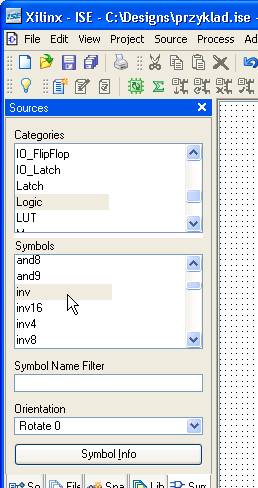
Here you will draw
the schematic diagram. The components can be found in the library, to the left
of the main window:
Connect the
elements using Add/Wire ![]() tool.
tool.
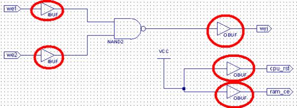
All the ports going outside the FPGA (inputs and outputs) should use the
corresponding buffers: (IBUF = input buffer, OBUF = output
buffer), i.e.:
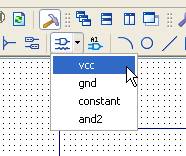
To generate constant value (logic 'zero' or 'one'), use the following button:
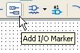
To add new ports,
the following button can be used:
Add/Wire ![]() draws single wires.
draws single wires.
To draw a bus,
first draw a wire, then add a bus name to the wire (i.e. data(7:0) )
with Add/Net Name ![]() :
:
- click on ![]()
- enter the bus
name in the window::
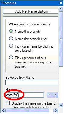
- click on the
wire, which will be changed into a bus.
To extract a
single wire from the bus, it is enough to give an appropriate name to this wire
going out from the bus, i.e. data(4). You can also use the tool Add/Bus
Tap ![]() .
.
When the schematic diagram is ready, save it ![]() .
.