Simulating the design
The procedure below is using
the schematic-based design with the circuit "moj_schemat.sch". For
HDL-based designs, the procedure is identical.
Create the file with stimulators
for the design under test. This can be achieved in two methods:
Method 1) (PREFFERED)
Write testbench in VHDL or Verilog – just create a new module/entity
i HDL language (without ports – they are not needed), then name it as i.e . testbench,
and finally instantiate the design under test inside the tesbench. The
stimulators are also generated in the testbench using HDL language.
Method 2) Using the tool Test
Bench Waveform:
Add new fiel to the design:
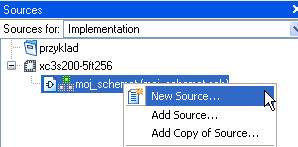
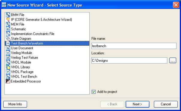
Select typ of the file Test
Bench Waveform and enter its name:
Select the file wich will be
simulated with your new testbench:
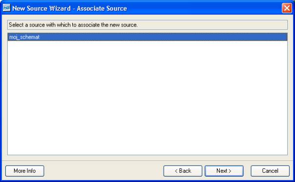
And press Finish.
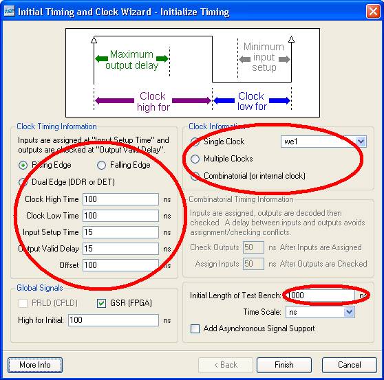
Enter stimulus details:
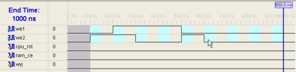
and draw the waveforms using in
graphical editor:
Finally save the file and
close the testbench GUI..
WARNING: It is recommended to
use method 1.
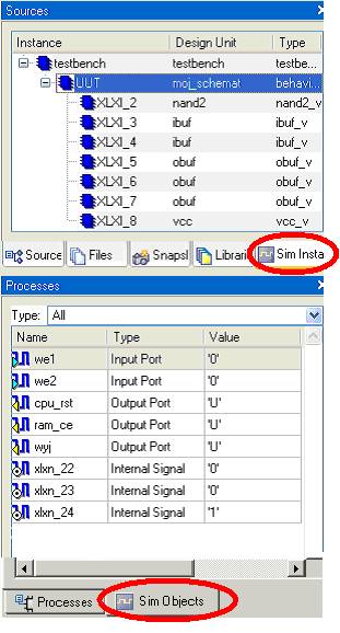
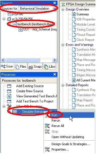
On the left side of the
screen, select Sources for: Behavioral Simulation, the select the file
for simulation (it must be your testbench) and in the Processes window,
start the simulation Simulate Behavioral Model:
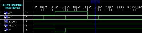
Utworzony zostanie model do
symulacji oraz otworzy się okno symulatora:
Buttons ![]() can be used for simulation control.
can be used for simulation control.
From the window on the left,
the arbitrary signals and ports from your design can be added (make sure, that Sim
Instances and Sim Objects tabs are selected). Having added a new
signal, the simulation must be restarted.