Embedded
Development Kit - PowerPC® Processor in FPGA
In this exercise you will implement the embedded system using FPGA and
PowerPC processor and run the Linux operating system on it. Then you will
implement a simple web server for remote LED control and switch status readout.
Run the EDK application (Embedded Development Kit icon at the desktop).
Following window will show up:
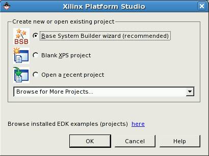
Choose option (default): Base System Builder wizard
Next window will show up:
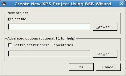
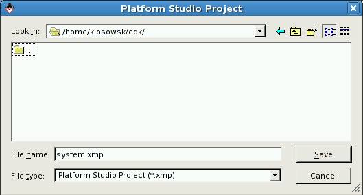
Click Browse ... button.
and create new project directory using button: ![]()
In this example the name of the project directory is edk.
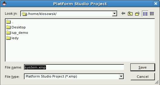
Then go to the created directory by clicking it:
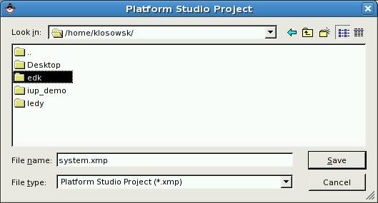
In the next step accept default project file name: system.xmp by
clicking Save button:
Then finally accept the new project by clicking OK button:
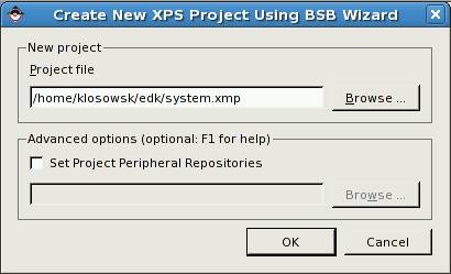
The system builder window opens now:
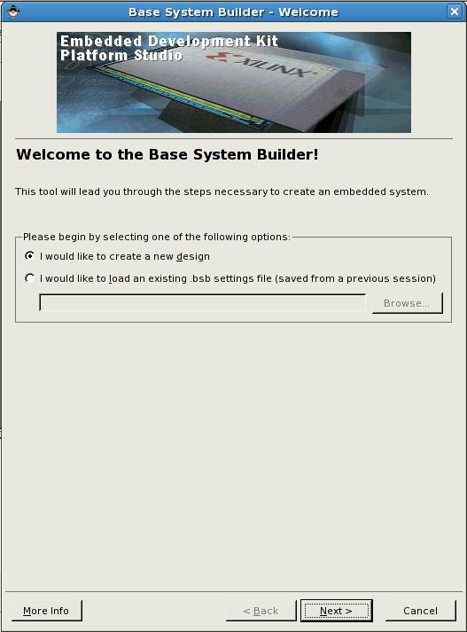
Accept by clicking Next.
Next window opens:
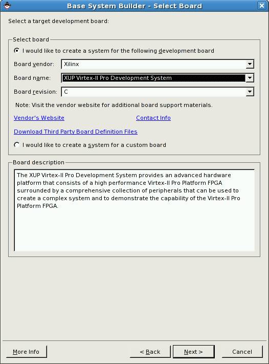
In the field Board vendor choose Xilinx, and in the field Board
name choose the name of the laboratory development board: XUP Virtex-II
Pro Development System.
Leave other fields intact and click Next. Next window shows up:
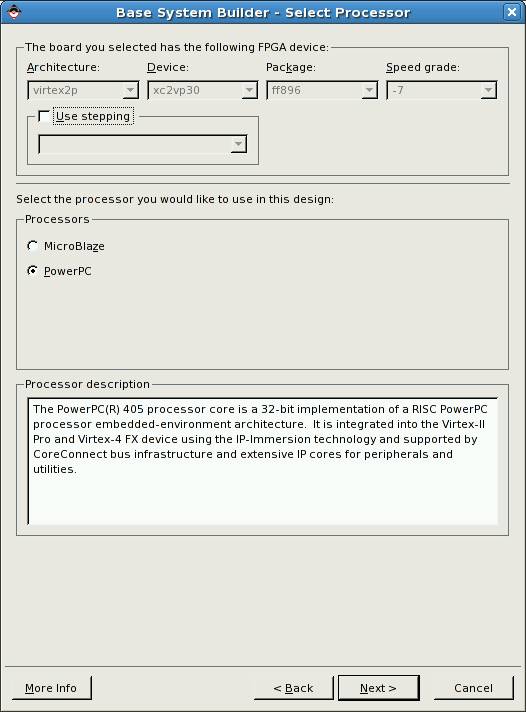
Nothing to change here - click Next (chosen processor is PowerPC).
Next window opens:
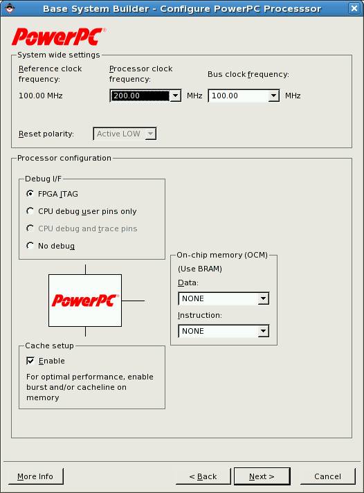
In the field Processor clock frequency choose 200.00 MHz,
in the field Cache setup mark Enable, and press Next.
Next window opens:
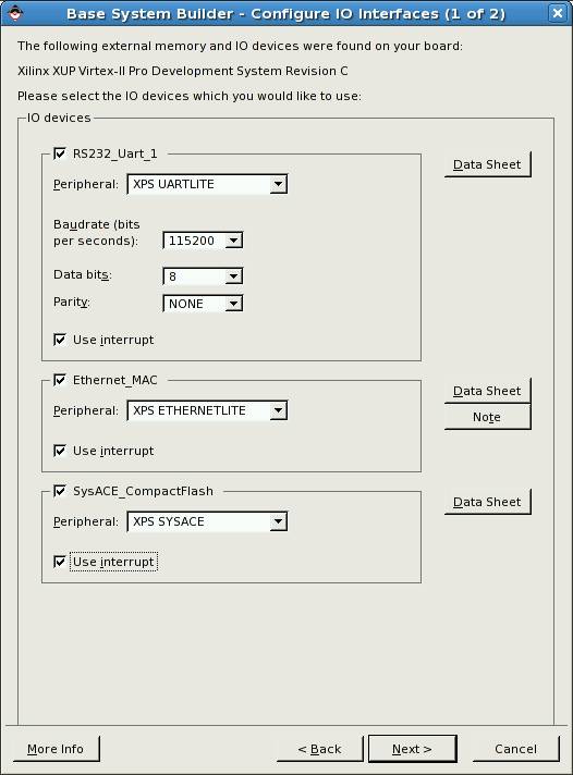
In the field Baudrate (bits per second): choose 115200, in
all fields enable interrupts by checking: Use interrupt. Then click Next.
Next window opens:
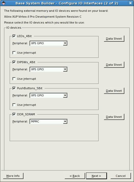
Leave this window intact and click
Next.
Next window opens:
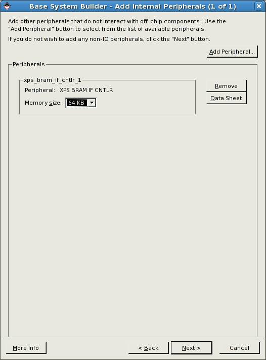
This is additional BRAM memory (Block RAM) – implemented in the FPGA, it
allows testing the main DDR memory and creating „bootloop” i.e. the infinite
loop stopping the processor after reset (this kind of memory can be initialized
along with the FPGA logic by the *.bit file). You can add to the project
optional devices like timer, watchdog or another BRAM memory (using the Add
Peripheral button). In this project however you don’t need additional
devices.
In the field Memory size choose 64 KB. Then
click Next.
Next window opens:

In this window you activate cache memory for selected code and data
storages:
Check ICache and Dcache for DDR_SDRAM memory.
Then click Next.
Next window opens:
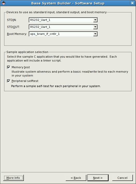
This window is for configuring console I/O device and the device mapped
to the boot address of the processor.
Leave this window intact and click Next.
Next window shows up:
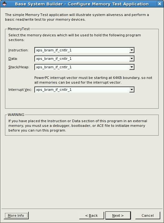
In this window you can map the memory devices to the memory sections of
sample program MemoryTest. This program can fit in the BRAM memory so you can
easy test all the DDR SDRAM memory. BRAM memory can be initialized along with
the hardware using the *.bit file.
Leave this window intact and click Next.
Next window will open:
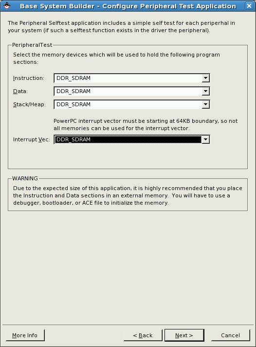
In this window you can map the memory devices to the memory sections of
sample program PeripheralTest. If DDR SDRAM is selected you will have to use
the debugger to initialize the memory.
In the field Interrupt Vec select DDR_SDRAM, then click Next.
Summary window will open:
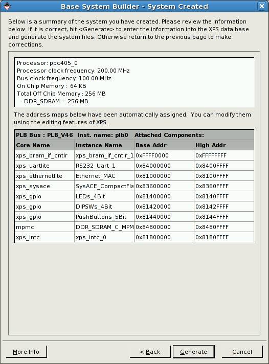
Click Generate button to generate the system you have
just configured.
Final window will open:
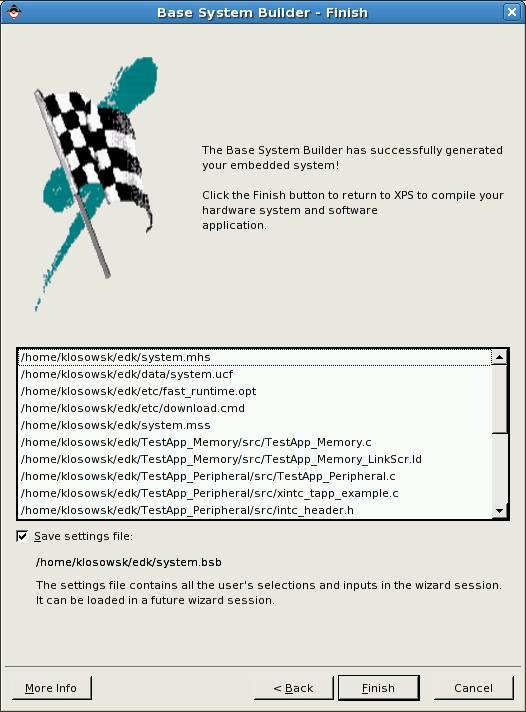
Click Finish button.
The main project window will open in a few seconds:
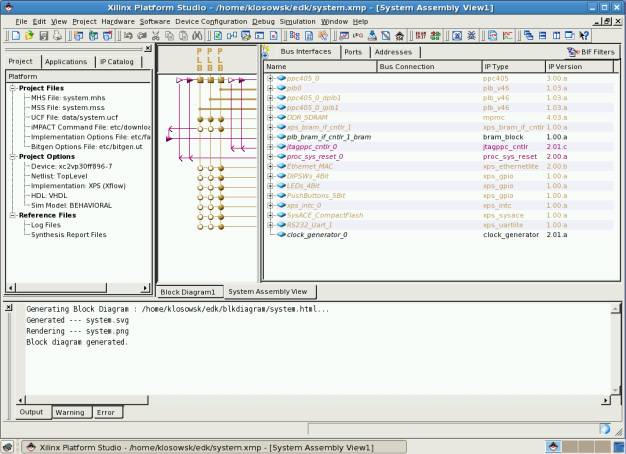
Before you begin the synthesis you need to do small modification to the
MAC Ethernet module. Double click on
the Ethernet_MAC in the window Bus Interfaces. New
configuration window will open:
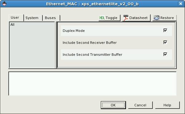
In this window check Include Second Receiver Buffer and Include
Second Transmitter Buffer. This modification increases performance of the
MAC thanks to double buffering (and it is needed to run Linux system later).
Then press OK.
After return to the main window you can finally start the synthesis:
In the main menu select: Hardware, and then: Generate Bitstream. Alternatively
you can just click ![]() button.
button.
The synthesis and implementation process should begin. Please wait about
20 minutes. There will be no need to repeat the process later.
After the synthesis and implementation is finished prepare the project
for the communication with Virtex2Pro development board. Click USB config in
EDK icon at the desktop. The script will search for EDK projects designed
for V2Pro board in the user’s home directory and will modify the project
control files to allow communication with the board using USB link. The script
will also copy device-tree files to the project directory – they will be needed
for building Linux kernel.
Now close the EDK (Xilinx Platform Studio) application, start it again
and open your project.
The system is ready. Now you can do the exercises with the laboratory
board:
Exercise 1:
Run the TestApp_Memory application in BRAM memory (FPGA build-in
memory).
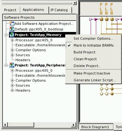
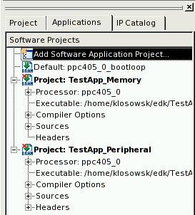
Click the Applications tab then click with right mouse button the
name of the project: TestApp_Memory and check Mark to Initialize
BRAMs. This will make the application loaded to the BRAM memory during
configuration of the FPGA and it will be started just after the configuration
is completed.
BRAM memory is limited (in our example to 64 kB). More advanced projects
will not fit in the BRAM memory. It is usually used only to keep small
bootloader application. When bootloader is not used, the BRAM memory is
initialized with small “bootloop” application – infinite loop which allows the
debugger to take control of the application after reset. The debugger can stop
the processor running bootloop application and then download the final
application to any available memory device.
TestApp_Memory is the
application for DDR SDRAM memory testing – it is small and fits in the BRAM
memory.
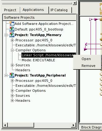
You can also browse the linker script where you can find the memory
mappings of all the sections of your application. The linker script is
generated automatically and in this exercise you do not need to modify it.
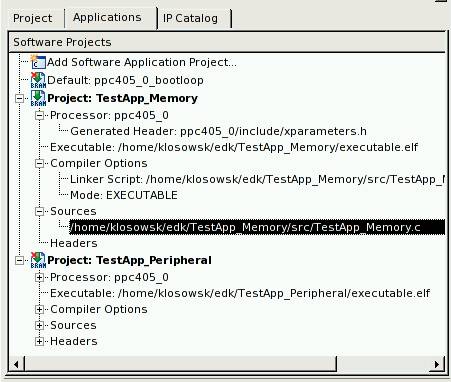
You can also edit project’s source files (*.c and *.h).
Special file xparameters.h contains definitions of the implemented
hardware (like memory addresses, interrupt numbers, etc.) and it should not be
modified by hand.
Now compile the software project – click the software project name with
the right mouse button and select Build Project (you can also do Clean
Project before). The software project will be compiled automatically when
the button for project download to the board is clicked: ![]()
Before loading the design to the laboratory board please run the MINICOM
application (icon at the desktop) and set the RS232 port speed to 115200
bps (CTRL-A Z P I <Enter>).
Check if the RS232 cable is connected to the V2Pro board (if not
disconnect it from the Spartan 3 board and connect to the V2Pro board).
Then click the ![]() button and observe the messages on the MINICOM
console.
button and observe the messages on the MINICOM
console.
Show the results to the instructor.
Exercise 2:
Now you will run the TestApp_Peripheral in the DDR SDRAM memory
and use the debugger application.
In the default bootloop project check the field Mark to Initialize
BRAMs (click with right mouse button: Default: ppc405_0_bootloop).
As you can see in the linker script the application is loaded to the DDR
SDRAM, only small part of code is loaded to the BRAM, it is a jump instruction
to the main application in the DDR SDRAM memory. Bootloop will hang the
processor until it will be changed to the jump instruction when the application
is loaded by the debugger.
Build the project like in the previous exercise.
Then send the hardware project with software bootloop to the V2Pro
board: (use button:![]() ). The
processor will wait in the bootloop.
). The
processor will wait in the bootloop.
Then run the debugger application: XMD (click button: ![]() ).
).
At the first execution the system will ask for some options:
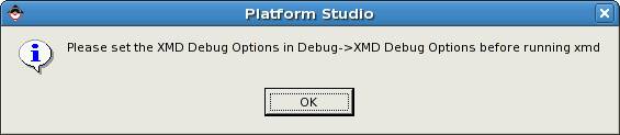
Confirm by clicking OK. Then the XMD configuration window will be
displayed.
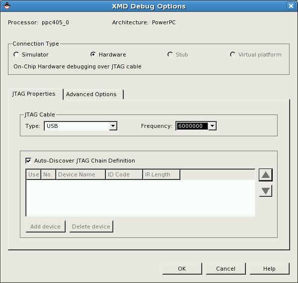
In
the field JTAG Cable please set:
Type: USB
Frequency: 6000000
Then click OK. This will start the XMD (in separate window).
Keep this application running.
Now you have to run the application debugger. Click the ![]() icon – the following menu is displayed:
icon – the following menu is displayed:
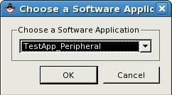
Choose TestApp_Peripheral and click
OK.
Then the application debugger window is displayed:
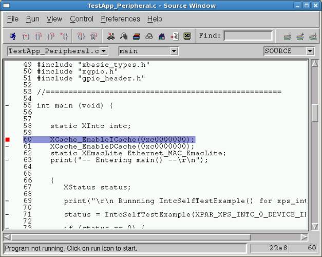
Now click the ![]() icon - the application will be loaded to the
memory and the program will run.
icon - the application will be loaded to the
memory and the program will run.
The program stops at the breakpoint (red square). This is default
breakpoint set at the beginning of the application. To continue the program
click ![]() (continue) button. All the peripheral tests
will be run (observe messages on the MINICOM console).
(continue) button. All the peripheral tests
will be run (observe messages on the MINICOM console).
After performing the tests program stops again at the next default
breakpoint location – the exit.
Show the results to the instructor.
Comments:
You can experiment with the debugger. Set other breakpoints, watch
variables, etc.).
If you want to load and start the program again click the icon: ![]()
There is a faster method of loading the application to the DDR SDRAM
memory and starting the application.
You can use the XMD command line:
XMD% cd TestApp_Peripheral
XMD% dow executable.elf
..............................
..............................
..............................
XMD% run
Exercise 3:
Write and launch your own program.
The task is to create a telnet control server application using the text
commands for controlling LEDs and reading DIP switches. To implement the
project you will use the uIP library (TCP/IP stack for micro-controllers: http://en.wikipedia.org/wiki/UIP_(micro_IP)).
Before creating a new project, set up a directory for it in which source
files will be stored. In this example the directory is: ~/edk/uip:
mkdir ~/edk/uip
Copy the files into this directory (please enter the following
commands):
cp /opt/uip-1.0/uip/* ~/edk/uip
cp /opt/uip-1.0/apps/telnetd/* ~/edk/uip
cp /opt/uip-1.0/unix/clock-arch.* ~/edk/uip
cp /opt/uip-1.0/unix/uip-conf.h ~/edk/uip
cp /opt/uip-1.0/lib/* ~/edk/uip
rm ~/edk/uip/uip-split.*
Now you can create a new project - click on Add Software Application
Project.
A window opens:
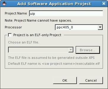
Give a name to the project by typing it in the Project Name field
(in our example the name is uip). Press the OK button.
Then, in the resulting new project tab, right-click on the Sources
field and select Add Existing Files.

Then add all *.c files from the project directory ~/edk/uip to the
project.
Similarly, add all header files (*.h) using the Headers field.
Modify the uip_conf.h file containing the TCP/IP stack
configuration.
In the line 107 change the value of the parameter UIP_CONF_BUFFER_SIZE
to 2000 (there is no need to save memory as in implementations using
micro-controllers).
Change the UIP_CONF_BYTE_ORDER parameter value to UIP_BIG_ENDIAN
in the line 114 (we are dealing with a big-endian processor).
Let's change the UIP_CONF_LOGGING value to 0 in the line
121.
In addition, in the lines 148/149 instead of webserver.h use telnetd.h.
Now let's write the main file: main.c integrating the uIP library
with Xilinx libraries for GPIO and Ethernet-MAC support.
The detailed operation of the program should be as follows:
MAC address of the device – 00:01:02:03:04:05
IP address of the device – 192.168.1.2 (IP address of the eth1 port of the lab computer is 192.168.1.1,
netmask is: 255.255.255.0).
Instead of inactive telnet server menu items:
stats - show network statistics
conn - show TCP connections
insert the following items:
leds - set LEDs
dip - show DIP switch setting
The leds command should require a 4-character string parameter
consisting of zeros and ones. Zero means the LED is off, one means the LED is
on. The leftmost string character should control the leftmost LED, etc. When
the application starts, all the LEDs should be off. Please remember to update
the help function. Test the application (ping and telnet should work).
Please show the results to the instructor.
Tips and recommendations to make the task easy:
- The uIP
documentation is located on the local disk:
/opt/uip-1.0/doc/html/index.html - The local
disk also contains an example of the main loop of the program (it can be
used in your own main.c):
/opt/uip-1.0/doc/example-mainloop-with-arp.c
It is configured for httpd - so you have to replace references to httpd with references to telnetd. The main loop of the program does not use interrupts. - Xilinx header
files that you will need:
#include "xparameters.h"
#include "xemaclite.h"
#include "xenv.h"
#include "xgpio.h"
#include "xtime_l.h"
file xparameters.h contains parameters of hardware components, their addresses in the memory, etc.,
file xemaclite.h includes parameters and structures related to support for the Fast Ethernet driver,
file xenv.h includes definitions of some useful functions, such as memcpy or memset,
file xgpio.h includes functions and structures related to Xilinx GPIO support,
file xtime_l.h includes definitions of functions that support the PowerPC built-in timer-counter. - Do not forget
to enable the cache memory:
XCache_EnableICache(0xc0000000);
XCache_EnableDCache(0xc0000000); - Xilinx
hardware modules documentation is available in the local file:
/opt/Xilinx/10.1/EDK/doc/usenglish/proc_ip_ref_guide.htm - Driver
documentation for Xilinx hardware modules is available in the local file:
/opt/Xilinx/10.1/EDK/doc/usenglish/xilinx_drivers_api_toc.htm
Information about version numbers of a driver can be acquired by clicking the icon: and choosing the field Drivers.
 - The Xilinx
system library documentation is available in the local file:
/opt/Xilinx/10.1/EDK/doc/usenglish/oslib_rm.pdf
You can find there also a description of the clock library xtime_l.h - A good source
of examples are also the test applications: TestApp_Memory i TestApp_Peripheral.
- Printing on
the console is accomplished by the xil_printf() function, which is
a simplified version of the standard printf() function.
- Develop the appropriate
wrapper functions that perform basic operations on the network device: network_device_send,
network_device_read i network_device_init.
- Do not forget
to set the MAC address also in the uIP library (the same as for the MAC
driver) using the uip_setethaddr(...) function.
- In the uip
documentation you can find the notice that the packet being sent should be
assembled from the two locations: uip_buf - Ethernet and TCP/IP headers
and uip_appdate - application data. In our example, the second pointer is
set at the end of the first buffer - so you can handle the frame
transmission at one time (a whole package of uip_len from uip_buf buffer).
- Support of
LED control and DIP-switch reading can be done by modifying the shell.c
file.
- Set GPIO
channel to 1 for output and for input.
- In the clock_arch.c
file modify the method of time measurement – the available method is to
use the build-in PowerPC timer-counter (xtime_l.h library).