Simple stopwatch
Task: The system should measure time with an accuracy of hundredths of a second. Subsequent presses of the BTNC button (start_stop_button_i) (in remote mode - virtual BTN0 button) trigger the following action:
Fig. 1 Operation of the stopwatch with successive presses of the
button.
The time should be displayed on the LED display in the form:
SS.DD, where: SS = seconds, DD = hundredths of a second. Exceeding the time of
59.99 seconds should be signaled by a special overflow symbol, eg
("--.--").
The BTNR (rst_i) button (in
remote mode - virtual BTN3 button) is an additional asynchronous
reset (should reset the stopwatch - display "00.00" and wait for
start).
Note: The stopwatch must be secured against vibration of the BTNC (BTN0) button. It can be assumed that after pressing the button the contacts of the button may vibrate for up to 50 ms.
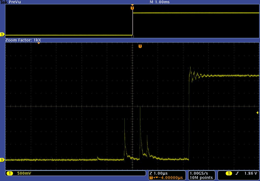
Fig. 2 An example of the voltage waveform while pressing the button.
The display control block from the previous exercise should be embedded as a component in the system.
Perform a functional simulation and verify the system practically by programming the test board.
Minimum
simulation and verification requirements: Perform the simulation and
verification to show start operation, stop operation (for verification after
any time - for simulation it should be a time equal to 1.xy seconds; where xy
are the last two digits of the student's index number) and reset operation of
the stopwatch (using start_stop_button_i). On-board verification should also
demonstrate overflow and overflow reset (using start_stop_button_i). At the end
of the verification, show the operation of the asynchronous reset input (rst_i)
while the timer is running. Clock frequency in the simulation - 100 MHz.
Note: In remote mode, when verifying the stopwatch on the board, please enable contact vibration emulation (select SW/BTN bouncing).
Part of the main (top level) VHDL design file with signal declaration:
entity top is
Port ( clk_i : in STD_LOGIC;
rst_i : in STD_LOGIC;
start_stop_button_i : in STD_LOGIC;
led7_an_o : out STD_LOGIC_VECTOR (3 downto 0);
led7_seg_o : out STD_LOGIC_VECTOR (7 downto 0));
end top;
Design
constraints file for Nexys-A7 board (FPGA chip xc7a100tcsg324-1): iup7s.xdc
Design constraints file for remote mode (with support for virtual buttons): iup7z.xdc