Embedded
Development Kit - PowerPC® Processor in FPGA
During this exercise you will implement embedded system using FPGA and
PowerPC processor and run the Linux operating system on it. Then you will
implement simple web server for remote LED control and switch status readout.
Run the EDK application (Embedded Development Kit icon at the desktop).
Following window will show up:
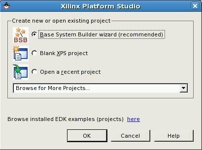
Choose option (default): Base System Builder wizard
Next window will show up:
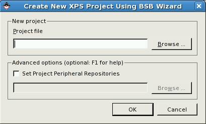
Click Browse ... button.
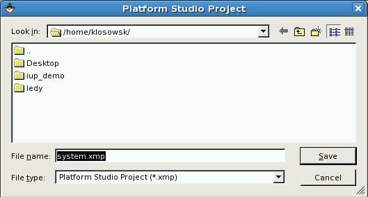
and create new project directory using button: ![]()
In this example name of the project directory is: edk.
Then go to created directory by clicking it:
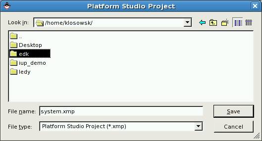
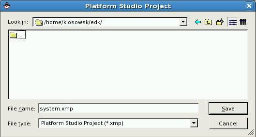
In the next step accept default project file name: system.xmp by
clicking Save button:
Then finally accept new project by clicking OK button:
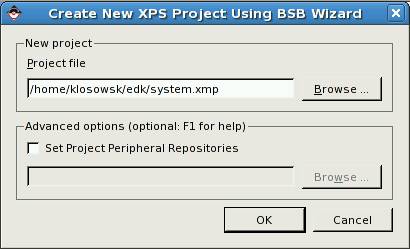
The system builder window is opened now:
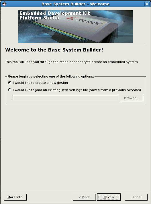
Accept by clicking Next.
Next window is opened:
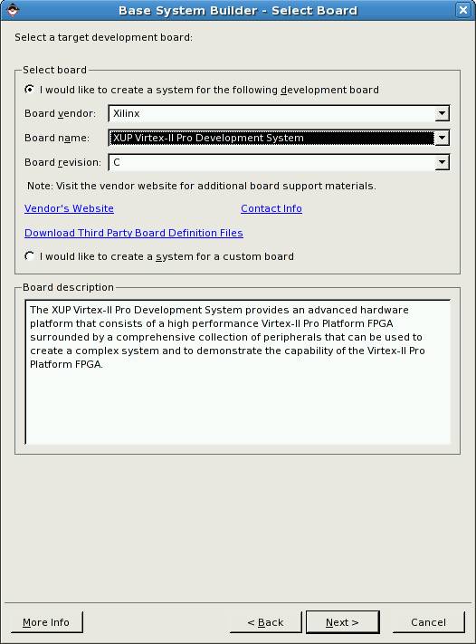
In the field Board vendor choose Xilinx, and in the field Board
name choose the name of the laboratory development board: XUP Virtex-II
Pro Development System.
Leave other fields intact and click Next. Next window is opened:
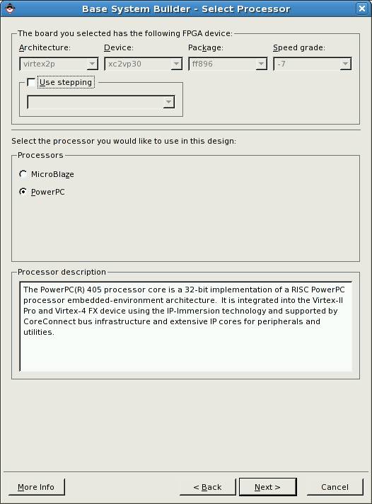
Nothing to change here - click Next (chosen processor is PowerPC).
Next window is opened:
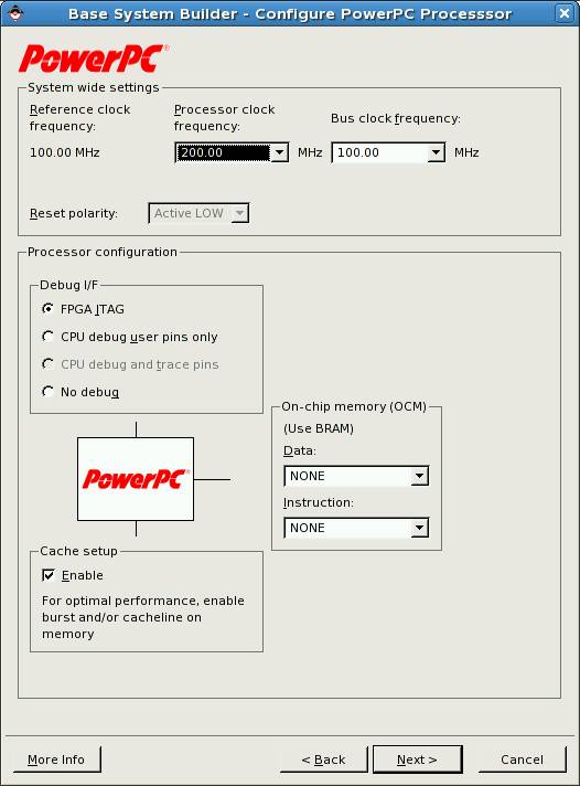
In the field Processor clock frequency choose 200.00 MHz,
in the field Cache setup mark Enable, and press Next.
Next window is opened:
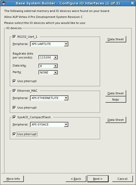
In the field Baudrate (bits per second): choose 115200, in
all fields enable interrupts by checking: Use interrupt. Then click Next.
Next window is opened:
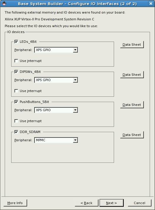
Leave this window intact and click
Next.
Next window is opened:
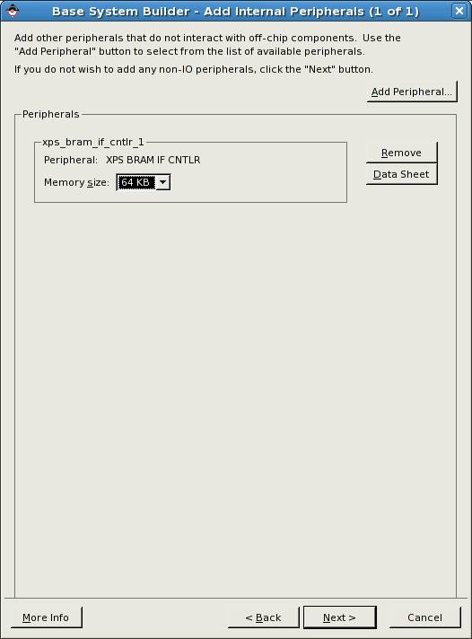
This is additional BRAM memory (Block RAM) – implemented in the FPGA, it
allows testing the main DDR memory and creating „bootloop” i.e. the infinite
loop stopping the processor after reset (this kind of memory can be initialized
along with the FPGA logic by the *.bit file). You can add to the project
optional devices like timer, watchdog or another BRAM memory (using the Add
Peripheral button). In this project however you don’t need additional
devices.
In the field Memory size choose 64 KB. Then
click Next.
Next window is opened:
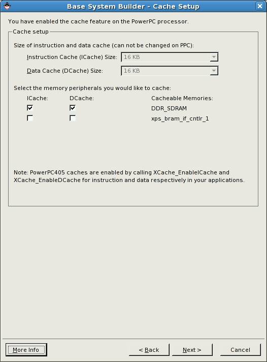
In this window you activate cache memory for selected code and data
storages:
Check ICache and Dcache for DDR_SDRAM memory.
Then click Next.
Next window is opened:
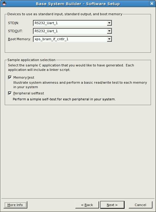
This window is for configuring console I/O device and the device mapped
to the boot address of the processor.
Leave this window intact and click Next.
Next window will show up:
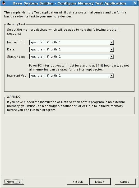
In this window you can map the memory devices to the memory sections of
sample program MemoryTest. This program can fit in the BRAM memory so you can
easy test all the DDR SDRAM memory. BRAM memory can be initialized along with
the hardware using the *.bit file.
Leave this window intact and click Next.
Next window will open:
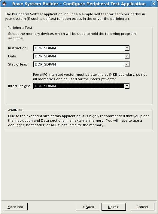
In this window you can map the memory devices to the memory sections of
sample program PeripheralTest. If DDR SDRAM is selected you will have to use
the debugger to initialize the memory.
In the field Interrupt Vec select DDR_SDRAM, then click Next.
Summary window will open:
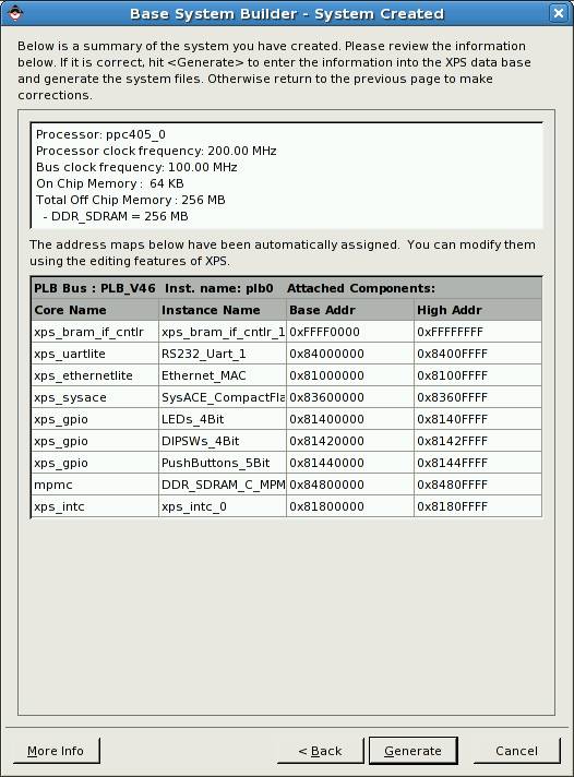
Click Generate button to generate the system you have
just configured.
Final window will open:
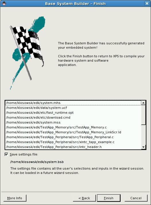
Click Finish button.
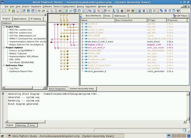
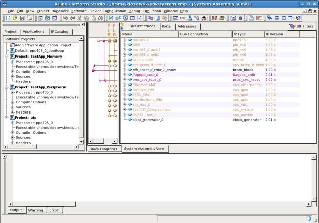
The main project window will open in a few seconds:
Before you begin the synthesis you need to do small modification to the
MAC Ethernet module. Double click on
the Ethernet_MAC in the window Bus Interfaces. New
configuration window will open:
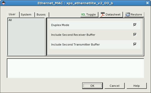
In this window check Include Second Receiver Buffer and Include
Second Transmitter Buffer. This modification increases performance of the
MAC thanks to double buffering (and it is needed to run Linux system later).
Then press OK.
After return to the main window you can finally start the synthesis:
In the main menu select: Hardware, and then: Generate Bitstream. Alternatively
you can just click ![]() button.
button.
The synthesis and implementation process should begin. Please wait about
20 minutes. There will be no need to repeat the process later.
After the synthesis and implementation is finished prepare the project for
the communication with Virtex2Pro development board. Click USB config in EDK
icon at the desktop. The script will search for EDK projects designed for V2Pro
board in the user’s home directory and will modify the project control files to
allow communication with the board using USB link. The script will also copy
device-tree files to the project directory – they will be needed for building
Linux kernel.
Now close the EDK (Xilinx Platform Studio) application, start it again
and open your project.
The system is ready. Now you can do the exercises with the laboratory
board:
Exercise 1:
Run the TestApp_Memory application in BRAM memory (FPGA build-in
memory).
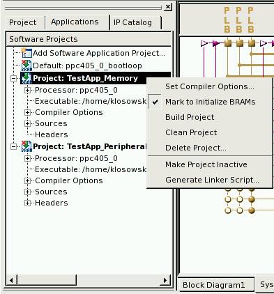
Click the Applications tab then click with right mouse button the
name of the project: TestApp_Memory and check Mark to Initialize
BRAMs. This will make the application loaded to the BRAM memory during
configuration of the FPGA and it will be started just after the configuration
is completed.
BRAM memory is limited (in our example to 64 kB). More advanced projects
will not fit in the BRAM memory. It is usually used only to keep small
bootloader application. When bootloader is not used, the BRAM memory is
initialized with small “bootloop” application – infinite loop which allows the
debugger to take control of the application after reset. The debugger can stop
the processor running bootloop application and then download the final
application to any available memory device.
TestApp_Memory is the
application for DDR SDRAM memory testing – it is small and fits in the BRAM
memory.
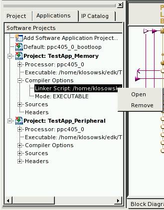
You can also browse the linker script where you can find the memory
mappings of different sections of you application. The linker script is
generated automatically and in this exercise you do not need to modify it.
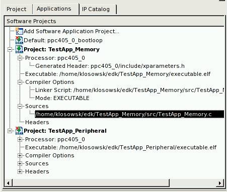
You can also edit project’s source files (*.c and *.h).
Special file xparameters.h contains definitions of the implemented
hardware (like memory addresses, interrupt numbers, etc.) and it should not be
modified by hand.
Now compile the software project – click the software project name with
the right mouse button and select Build Project (you can also do Clean
Project before). The software project will be compiled automatically when
the button for project download to the board is clicked: ![]()
Before loading the design to the laboratory board please run the MINICOM
application (icon at the desktop) and set the RS232 port speed to 115200
bps (CTRL-A Z P I <Enter>).
Check if the RS232 cable is connected to the V2Pro board (if not
disconnect it from the Spartan board and connect to the V2Pro board).
Then click the ![]() button and observe the messages on the MINICOM
console.
button and observe the messages on the MINICOM
console.
Show the results to the instructor.
Exercise 2:
Now you will run the TestApp_Peripheral in the DDR SDRAM memory
and use the debugger application.
In the default bootloop project check the field Mark to Initialize
BRAMs (click with right mouse button: Default: ppc405_0_bootloop).
As you can see in the linker script the application is loaded to the DDR
SDRAM, only small part of code is loaded to the BRAM, it is a jump instruction
to the main application in the DDR SDRAM memory. Bootloop will hang the
processor until it will be changed to the jump instruction when the application
is loaded by the debugger.
Build the project like in previous exercise.
Then send the hardware project with software bootloop to the V2Pro
board: (use button:![]() ). The
processor will wait in the bootloop.
). The
processor will wait in the bootloop.
Then run the debugger application: XMD (click button: ![]() ).
).
At the first run the system will ask for some options:
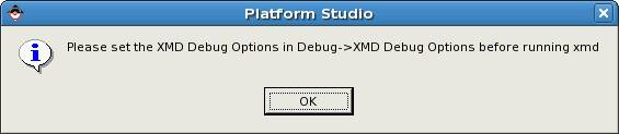
Confirm by clicking OK. Then the XMD configuration window will be
displayed.
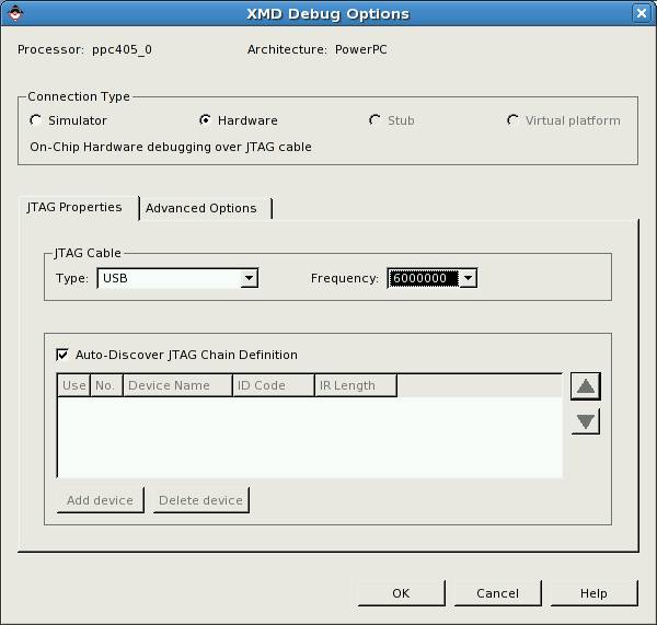
In
the field JTAG Cable please set:
Type: USB
Frequency: 6000000
Then click OK. This will start the XMD (in separate window).
Keep this application running.
Now you have to run the application debugger. Click the ![]() icon – the following menu is displayed:
icon – the following menu is displayed:
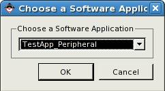
Choose TestApp_Peripheral and click
OK.
Then the application debugger window is displayed:
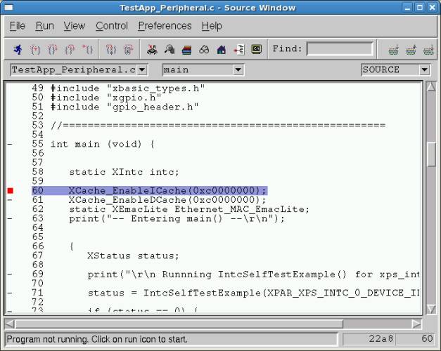
Now click the ![]() icon - the application will be loaded to the
memory and the program will run.
icon - the application will be loaded to the
memory and the program will run.
The program stops at the breakpoint (red square). This is default
breakpoint set at the beginning of the application. To continue the program
click ![]() (continue) button. All the peripheral tests
will be run (observe messages on the MINICOM console).
(continue) button. All the peripheral tests
will be run (observe messages on the MINICOM console).
After tests program stops again at the next default brakpoint location –
the exit.
Show the results to the instructor.
Comments:
You can experiment with the debugger. Set other breakpoints, watch
variables, etc.).
If you want to load and start the program again click the icon: ![]()
There is a faster method of loading the application to the DDR SDRAM
memory and starting the application.
You can use the XMD command line:
XMD% cd TestApp_Peripheral
XMD% dow executable.elf
..............................
..............................
..............................
XMD% run
Exercise 3:
Now you will run the Linux operating system.
This is your current EDK window:
Now you will configure the EDK to generate the device tree. The device
tree holds hardware configuration data needed by Linux kernel (the kernel uses
device tree to access devices at proper addresses, interrupts, etc.).
Click menu Software and then Software Platform Settings
(or icon: ![]() ).
).
New window will show up:
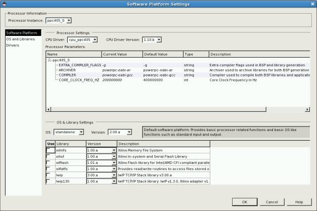
In the field OS:
change standalone to device-tree.
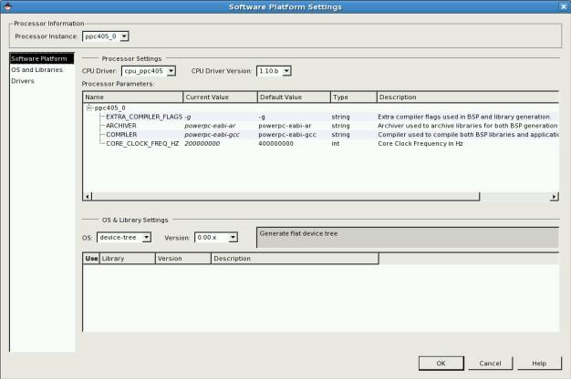
Then click OS and Libraries:
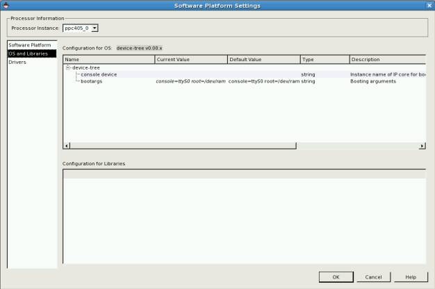
Now, in the field console device write: RS232_Uart_1
In the field bootargs
change: console=ttyS0 to console=ttyUL0
(we are using UartLite in place of standard 16550).
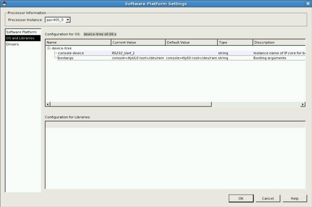
Then click OK.
Click Software and then Generate Libraries and BSPs (or the icon: ![]() ).
).
This will generate the file: xilinx.dts containing the device tree.
This file will be written to the directory (under the project main
directory):
ppc405_0/libsrc/device-tree_v0_00_x
Now you will compile the Linux kernel.
Open the terminal and (in the home directory) run the script:
linux-kernel-copy
This script will copy the Linux kernel distribution directory to your
home directory.
Then in the terminal window run the command:
source source_me
This will set all needed environment variables for PowerPC C compiler.
Then enter the Linux Kernel distribution directory:
cd linux-2.6-xlnx
and run the configuration manager:
make menuconfig
new window will be displayed:
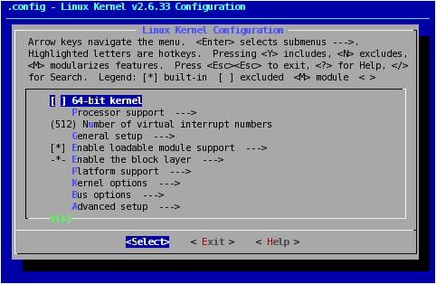
Main settings (like processor version) are already properly prepared.
You only have to enable GPIO access:
To enable GPIO choose option:
Device Drivers --->
And press ENTER.
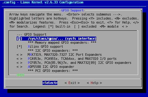
Then choose next option:
GPIO Support --->
And press ENTER.
Then check the following position (using SPACE):
/sys/class/gpio/... (sysfs interface)
The asterisk symbol (*) means the option is checked:
Then press Exit several
times, when the save confirmation is displayed press Yes – the application will be closed and current
configuration will be written to the .config file.
Now you must copy previously generated file with device tree: (it is
assumed that edk is your current project directory):
cp
~/edk/ppc405_0/libsrc/device-tree_v0_00_x/xilinx.dts ~/linux-2.6-xlnx/arch/powerpc/boot/dts/virtex405-lab.dts
Then copy the file with root filesystem for Linux:
cp
/opt/buildroot/initrd.patched.ext2.gz
~/linux-2.6-xlnx/arch/powerpc/boot/ramdisk.image.gz
Now you can begin the kernel compilation process
(your current directory should be: linux-2.6-xlnx):
make -j
2 simpleImage.initrd.virtex405-lab
Build process takes about 8 minutes. Compiled kernel is copied to the following
file:
~/linux-2.6-xlnx/arch/powerpc/boot/simpleImage.virtex405-lab.elf
Now you will run the Linux on the Development Board.
You do not have to start EDK system. You can download
the bit file to the FPGA using following commands (it is assumed that edk is
your project directory):
cd ~/edk
impact
-batch etc/download.cmd
rlwrap
-c xmd -opt etc/xmd_ppc405_0.opt
This procedure will download *.bit file generated
previously and then start the XMD debugger in separate window. The connection
to the board will be created automatically.
Run the MINICOM and check if the connection speed is 115200
bps (if not use following commands to change it: CTRL-A Z P I <Enter>.).
Now in the XMD window (prompt XMD%) enter following
commands:
cd
~/linux-2.6-xlnx/arch/powerpc/boot
dow
simpleImage.initrd.virtex405-lab.elf
run
This procedure is faster than loading the kernel file
by software debugger.
After the system is loaded log on as user root
(without password) at MINICOM console.
Mount your home directory from the laboratory PC
(enter your login in place of dots):
mount -o
rsize=1500,wsize=1500 192.168.1.1:/home/...
/mnt
You can also mount the application directory (you can
use host names or IP numbers, for example: labhost or 192.168.1.1 is the
address of the second network card of laboratory PC):
mount -o
rsize=1500,wsize=1500 labhost:/opt_local
/opt
System Linux running on PowerPC (FPGA) has IP network
address: 192.168.1.2 and host name: xilinx.
rsize and wsize options limit the packet length to
the standard Ethernet packet, (to avoid
packet fragmentation and performance penalty) – the MAC controller in the FPGA
doesn’t support large frames.
GPIO support at userspace
level (suggested solution):
To try the access to the LEDs and switches on the
development board change current directory:
cd
/sys/class/gpio
Then display directory contents:
ls –al
total 0
drwxr-xr-x
5 root root 0 May
8 23:32 .
drwxr-xr-x
15 root root 0 May
8 23:32 ..
--w-------
1 root root 4096 May
9 02:23 export
drwxr-xr-x
2 root root 0 May
8 23:38 gpiochip243
drwxr-xr-x
2 root root 0 May
8 23:38 gpiochip248
drwxr-xr-x
2 root root 0 May
8 23:38 gpiochip252
--w-------
1 root root 4096 May
9 02:42 unexport
gpiochipxxx directories contain information about available GPIO
devices.
To be accessible GPIO ports have to be exported to
the user first. You can achieve this by writing port id to the export file.
Ports are one bit wide and have following ids:
Push buttons (5 ports): 243-247
LEDs (4 ports): 248-251
Switches (4 ports): 252-255
# ls
export
gpiochip243 gpiochip248 gpiochip252
unexport
# echo 248 > export
# ls
export
gpio248 gpiochip243 gpiochip248
gpiochip252 unexport
New catalog has been created due to export command: gpio248
This catalog contains files for exported GPIO bit
control:
# cd gpio248
# ls
active_low
direction subsystem uevent
value
Set the port direction to out:
# echo out > direction
Now you can write the logic value to the port:
# echo 1 > value
# echo 0 > value
Or you can switch the port direction to in
and read the logic value from the port by reading the value file
contents.
Now unexport the port:
# cd ..
# echo 248 > unexport
# ls
export
gpiochip243 gpiochip248 gpiochip252
unexport
Below simple script for LED and switch control is
presented:
(LEDs blink, state of the switches is printed every 2
seconds):
#!/bin/sh
cd /sys/class/gpio
echo "248" > export
echo "249" > export
echo "250" > export
echo "251" > export
echo "252" > export
echo "253" > export
echo "254" > export
echo "255" > export
echo out > gpio248/direction
echo out > gpio249/direction
echo out > gpio250/direction
echo out > gpio251/direction
echo in > gpio252/direction
echo in > gpio253/direction
echo in > gpio254/direction
echo in > gpio255/direction
while true ; do
sleep
1
echo 0
> gpio248/value
echo 1
> gpio249/value
echo 0
> gpio250/value
echo 1
> gpio251/value
sleep
1
echo 1
> gpio248/value
echo 0
> gpio249/value
echo 1
> gpio250/value
echo 0
> gpio251/value
echo
-n `cat gpio252/value`
echo
-n `cat gpio253/value`
echo
-n `cat gpio254/value`
echo `cat gpio255/value`
done
When exiting the application outputs should be
disabled (direction switched to in) and ports should be
unexported:
#!/bin/sh
cd /sys/class/gpio
echo in > gpio248/direction
echo in > gpio249/direction
echo in > gpio250/direction
echo in > gpio251/direction
echo "248" > unexport
echo "249" > unexport
echo "250" > unexport
echo "251" > unexport
echo "252" > unexport
echo "253" > unexport
echo "254" > unexport
echo "255" > unexport
It is of course possible to access GPIO using other
scripting languages (like TCL) or compiler languages (like C, C++, etc.) – you
just use the file system interface of the chosen language.
Task: implementation of mini
web server for remote LED control and switch status readout
Use simplified httpd server available in the PowerPC
Linux system (/usr/sbin/httpd).
Write simple CGI application for GPIO control and
integrate it with web server.
CGI can be written in scripting language (shell ash –
simplified version of bash), in TCL language (tclsh8.4), in C language (simple
hello-world compilation example presented below).
Additional information about CGI can be found below:
·
CGI in TCL: http://expect.nist.gov/doc/cgi.pdf
·
CGI in ash: http://isquared.nl/index.html?pagelink=9&desc=bourne/_bash_shell_cgi_scripts
·
CGI in C: http://www.cs.tut.fi/~jkorpela/forms/cgic.html
httpd is a simplified www server:
Usage: httpd [-ifv[v]] [-c CONFFILE] [-p
[IP:]PORT] [-u USER[:GRP]] [-r REALM] ]
or httpd -d/-e/-m STRING
Listen for incoming HTTP requests
Options:
-i Inetd mode
-f Don't daemonize
-v[v] Verbose
-c FILE Configuration
file (default httpd.conf)
-p [IP:]PORT Bind to ip:port
(default *:80)
-u USER[:GRP] Set uid/gid after
binding to port
-r REALM Authentication
Realm for Basic Authentication
-h HOME Home directory
(default .)
-m STRING MD5 crypt STRING
-e STRING HTML encode
STRING
-d STRING URL decode STRING
You can run the server this way:
httpd -h
home_directory_of_www_page
CGI scripts should be placed in subdirectory
/cgi-bin/
You can also write the configuration file for the
server, sample configuration file is presented below:
H:/serverroot # define the server root. It will
override -h
A:172.20. # Allow address from 172.20.0.0/16
A:10.0.0.0/25 # Allow any address from
10.0.0.0-10.0.0.127
A:10.0.0.0/255.255.255.128 # Allow any address that previous set
A:127.0.0.1 # Allow local loopback connections
D:* # Deny from other IP
connections
E404:/path/e404.html #
/path/e404.html is the 404 (not found) error page
I:index.html # Show index.html when a directory is requested
P:/url:[http://]hostname[:port]/new/path
# When /urlXXXXXX is requested, reverse proxy
# it to http://hostname[:port]/new/pathXXXXXX
/cgi-bin:foo:bar # Require user foo, pwd bar on urls starting
with /cgi-bin/
/adm:admin:setup # Require user admin, pwd setup on urls
starting with /adm/
/adm:toor:PaSsWd # or user toor, pwd PaSsWd on urls starting
with /adm/
.au:audio/basic # additional mime type for audio.au files
*.php:/path/php # run xxx.php through an interpreter
A/D may be as a/d or
allow/deny - only first char matters.
Deny/Allow IP logic:
- Default is to allow all (Allow all (A:*) is a no-op).
- Deny rules take precedence over allow rules.
- "Deny all" rule (D:*) is applied last.
Example:
1. Allow only specified addresses
A:172.20 #
Allow any address that begins with 172.20.
A:10.10. #
Allow any address that begins with 10.10.
A:127.0.0.1 #
Allow local loopback connections
D:* #
Deny from other IP connections
2. Only deny specified addresses
D:1.2.3. # deny
from 1.2.3.0 - 1.2.3.255
D:2.3.4. # deny
from 2.3.4.0 - 2.3.4.255
A:* #
(optional line added for clarity)
If a sub directory contains
a config file it is parsed and merged with any existing settings as if it was
appended to the original configuration.
subdir paths are relative to
the containing subdir and thus cannot affect the parent rules.
Note that since the sub dir
is parsed in the forked thread servicing the subdir http request, any merge is
discarded when the process exits.
As a result, the subdir
settings only have a lifetime of a single request.
Custom error pages can
contain an absolute path or be relative to 'home_httpd'. Error pages are to be
static files (no CGI or script).
Error page can only be
defined in the root configuration file and are not taken into account in local
(directories) config files.
If -c is not set, an attempt
will be made to open the default root configuration file. If -c is set and the file is not found, the
server exits with an error.
Show the running server to the instructor.
Appendix -
Compilation of C program for
PowerPC (for CGI in C):
Compilation is performed on the PC, then using the
home directory, which can be mounted on PowerPC Linux system, you can easily
run the compiled program on the laboratory board.
Run the following command in the terminal window:
source source_me
Create main.c file.
For example:
#include
<stdio.h>
main()
{
printf("Hello World!\n");
}
Then compile it using static linkage:
ppc_4xx-gcc
main.c -o main -static
Now you can start compiled program in MINICOM window.