Floorplanner
Exercise description:
Before you use the floorplanner to manually place components and
primitives on the FPGA you have to prepare design which you will later
floorplan.
The design is simple: design 2 ring-oscillators and frequency meter, then
precisely trim the placement of those two oscillators to acquire highest
possible oscillation frequency. Also those 2 ring oscillators should have as
similar frequency as possible.
The RO should be tested using frequency meter implemented in the FPGA.
The frequency meter module should send the results to the RS232 port for
verification.
Below example of how messages sent to RS232 port should be formatted is
presented:
….
….
RO1=185465 kHz
RO2=193094 kHz
RO1=185472 kHz
RO2=193087 kHz
….
….
Data should be sent using 115200 bps, no parity, 1 stop bit. Remember to
set the MINICOM communication parameters as well.
Delay between measurements should be about 1s.
Frequency of 2 ring oscillators should be displayed one after another in
infinite sequence (notice the small difference between consecutive measurements
of the same RO – they are present because of the jitter in the oscillator loop,
and will be used in the second part of the exercise to generate the random
numbers).
Suggested frequency meter’s input circuit is presented below (4-stage
ripple counter is used as a prescaler and a double FF signal synchronizer is
implemented before synchronous frequency counter to prevent metastability):
In the second part of the exercise simple True Random Number Generator
(TRNG) should be implemented. Use two previously implemented ring oscillators
and connect them to the input of the XOR gate. Output of the XOR gate should be
sampled by a 50 MHz clocked D flip-flop (use another D flip-flop in sequence to
get rid of possible metastability).
The bit stream from the second flip-flop’s Q output can be considered
random. Of course this is simple TRNG and it is quite possible that there will
be some bias or other imperfections – in practical situations additional
resilience function should be used to process the bit stream.
The switch on the board should be used to send the output of the TRNG to
the previously implemented RS232 asynchronous transmitter module (the TRNG will
be sampled by the transmitter module with frequency of the RS232 baud rate –
which means that random data will have better quality, because it is a simple
resilience function).
Before you switch the output of the board’s RS232 port to the random
stream, close the MINICOM using the closing command CTRL-A Q. Using this
kind of exit is important because it leaves all the communication port settings
unchanged – the speed, line discipline
and other parameters are left in the state taken from MINICOM session.
Capture the random stream from RS232 port using the shell command:
dd bs=1 if=/dev/ttyS0 of=randomfile count=4000000
The file with random 32-bit integers will be created. The size of the file
should be 4MB. This of course can take a while.
After the data has been transferred you can perform some tests. Because
tests are time consuming you should perform only small subset of them.
dieharder –g 201 –f randomfile <test_number>
Suggested tests: -d 1, -d 5, -d 6, -d 7, -d 8, -d 9, -d 11, -d 12, -d
13, -d 15,
-r 2, -s 1, -s 2, -s 3
Warning:
The test file is too short for some tests – this can make the test fail
because the testing software will “rewind” the file and use it many times
reducing the quality of randomness in the file. You can try to reduce the
number of rands used in the test using the “t” option.
Inputs and outputs of the circuit:
clk_i – system clock 50MHz (quartz oscillator),
rst_i – asynchronous reset,
RXD_i – data input RS232,
TXD_o – data output RS232,
sw_i – switch to change the RS232 output (frequency meter or TRNG) (SW0 on
the board).
Detailed description:
For project implementation you will need access to primitives of the
FPGA. You will need the LUT (Look Up Table) – the basic programmable logic
module. When you instantiate LUTs you can program them to be inverters.
You can learn how to instantiate the primitives from the Language
Templates (choose menu Edit and submenu Language Templates).
Then find LUT1 (one input LUT) as presented below:
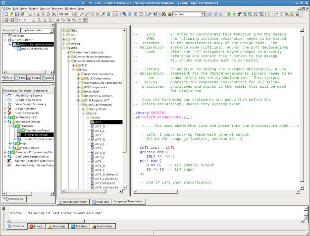
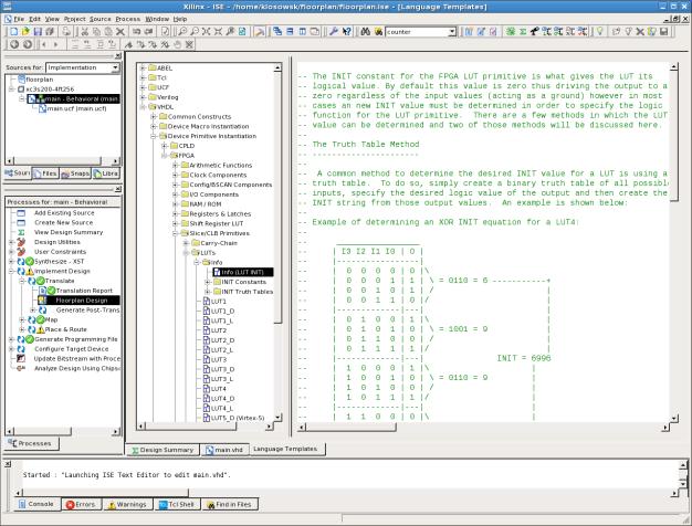
Remember to define the logic function of the instantiated LUT.
Detailed instruction can also be found in Language Templates:
After instantiation connect LUTs to form a Ring Oscillator.
Important!
Due to limitations in the synthesizer you need to include additional
gating in the loop of RO. Failing to do so can make the synthesizer to hang.
The gating in the loop can also be used as the enable input and make the RO to
start from defined state. During system configuration the RO should be
disabled. The gate can be 2-input LUT or it can be synthesized using conditional
assignment in the architecture description.
After the VHDL level design is ready perform the synthesis and the
implementation up to the TRANSLATE level.
Then start the “Floorplan design” under the Implementation →
Translate submenu. Please wait a moment until the Floorplanner shows up:
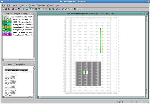
In the Design Hierarchy window you can find the list of all
primitive components in your design. At the beginning find the instance names
of the LUTs composing the RO and mark them (using left mouse button holding
CTLR key pressed). Alternatively you can use Edit→Find and
click Select Found after searching.
When LUTs are marked click Hierarchy→Group and the
new group containing LUTs will be created. You can change the name of the
group: mark the group you want to rename in the Design Hierarchy window
and then use Edit→Properties to change the name of the
group. Using groups is very convenient because you can floorplan the primitives
of the group together at once and in predictable order and pattern (see menu
option: Floorplan→Distribute Options).
Then select and drag the group to the Editable Floorplan window
to desired location. Of course you can drag single primitives as well.
Use a mouse to fine tune the placement, try to acquire shortest loop
path for Ring Oscillator.
Also, it is good idea to make the nearest surroundings of the RO free
from other primitives. To make an area prohibited for placement use menu
function: Floorplan→Prohibit and draw rectangle area in the
Editable Floorplan window (or click single CLB). To enable the placement
in the area use: Floorplan→Allow.
When you want to remove primitive from manual placement mark it using
the mouse and use the option: Floorplan→Remove.
After the manual placement is done, you have to write the manual
floorplan results to the UCF file for later processing.
To write the results to the UCF file use menu option: File→Write Constraints
(check if the name of the file is correct).
Inspect the file after that operation and locate new constrains adder by
floorplanner. You can place such constrains manually in the UCF file but using
the floorplanner is much more convenient.
HINT: Because of software bug you have to move slightly the “Save
Constraints As” window to make the window react to the buttons. Other file
manipulation windows and ”Edit→Preferences” window need the
same workaround.
When UCF file is written you can also write the Floorplanner’s data file
*.FNF using File→Write(As) menu function.
Next, resume the implementation sequence - the translate step may be repeated.
When the implementation is ready you can load the actual design
floorplan using: File→Update Design menu option (find the
*.ncd) file. The new “Placement” window will be opened.
Sometimes in the last phase of design you can use the final automatic
placement as a source for manual placement. Then you can make some manual
corrections to the placement, and the entire system floorplanning remains
fixed. To do so you use menu function: Floorplan→Replace All
with placement. This function copies (and overwrites) all placement data
from “Placement” window to “Editable Floorplan” window. You can also use Floorplan→Constrain
from placement if you want to only
copy the selected placement data to the “Editable Floorplan” window.
Other useful functions of floorplanner:
Floorplan→Check Floorplan… - for checking current
floorplan for possible warnings and problems.
Edit→Add Block – for creating hierarchy in the Design Hierarchy
window (you can rename new block after you create it and you can move some
primitives to it) – new blocks are similar to directories in the file system.
Pattern→Capture – you can select some previously placed primitives
and use this function to remember the pattern of the primitives.
Pattern→Impose – when you previously did pattern capture you can
impose the remembered pattern on some newly placed primitives by selecting them
and using this function.
Pattern→Flip Vertical
Pattern→Flip Horizontal – you can flip the selected primitives.
Circuit verification:
Check the frequency read-out of two ring oscillators. Frequency should
be more than 150 MHz and the difference between two oscillators should be less
than 10%. There should be small difference between consecutive
measurements (difference on no more
than 2 least significant digits). The random number file should be successfully
downloaded and successfully tested on about 50% of the suggested “dieharder”
tests.
Informacje dodatkowe o standardzie
RS232:
http://www.fizyka.umk.pl/~ptarg/labview/folie/RS232.pdf
http://pl.wikipedia.org/wiki/RS-232
Plik ucf do zadania, płytka Digilent
Spartan-3, układ Spartan-3 3S200 FT256-4:
# Clock:
NET "clk_i" LOC = "T9" ; # 50 MHz clock
#
# Push-buttons:
NET "rst_i" LOC = "L14" ; # pressed high BTN3
#
# RS232:
NET "TXD_o" LOC = "R13" ; # RS 232 TXD
NET "RXD_i" LOC = "T13" ; # RS 232 RXD
#
# Slide switch sw0:
NET "sw_i"
LOC = "F12" ; # active high when in UP position
#