
Lab Home page
|
Department of Microelectronic Systems, Faculty of Electronics,
Telecommunications and Informatics, Gdansk University of Technology
|

|
Sensor network for traffic monitoring
This work was supported in part by the Polish Ministry of Science and Higher Education under
R&D grant no. R02 014 01.
Contents
-
M. Wójcikowski, R. Żaglewski, B. Pankiewicz, M. Kłosowski, S. Szczepański,
"Hardware-Software Implementation of a Sensor Network for City Traffic Monitoring Using the FPGA- and ASIC-Based Sensor Nodes",
Journal of Signal Processing Systems, vol. 71, issue 1, Apr. 2013, pp.57-73.
-
M. Wójcikowski, R. Żaglewski, B. Pankiewicz,
"FPGA-Based Real-Time Implementation of Detection Algorithm for Automatic Traffic Surveillance Sensor Network",
Journal of Signal Processing Systems, vol. 68, issue 1, pp. 1-8, 2012.
- M. Musial, D. Dybek, M. Wojcikowski "Hardware realization of shadow detection algorithm in FPGA"
Information Technology (ICIT), 2010 2nd International Conference on
Publication Year: 2010 , Page(s): 201 - 204.
- M. Wojcikowski, R. Zaglewski, B. Pankiewicz, "An intelligent image processing sensor -
the algorithm and the hardware implementation", in Proc. Int. Conf. Information Technology,
Gdansk, Poland, 2008.
- R. Zaglewski, M. Wojcikowski, "Multi-core processor system for real-time image processing
in embedded computer vision applications",
Information Technology, 2008. IT 2008. 1st International Conference on
Digital Object Identifier: 10.1109/INFTECH.2008.4621604
Publication Year: 2008 , Page(s): 1 - 4
- M. Wojcikowski, R. Zaglewski, B. Pankiewicz, "An intelligent image processing sensor - the
algorithm and the hardware implementation"
Information Technology, 2008. IT 2008. 1st International Conference on
Digital Object Identifier: 10.1109/INFTECH.2008.4621663
Publication Year: 2008 , Page(s): 1 - 4
Simulation results of blob recogniton:
- City
 -Matlab simulation
- Speedway 1
-Matlab simulation
 -original frames
-ground truth frames
-results from C software, identical to hardware
-original frames
-ground truth frames
-results from C software, identical to hardware
- Speedway 2
-Matlab simulation
-original frames
-ground truth frames
- Speedway 3
-Matlab simulation
- Speedway 4
-Matlab simulation
- Speedway 5
-Matlab simulation
- Speedway 6
-Matlab simulation
-results from C software, identical to hardware
- Speedway 7
-Matlab simulation
- Speedway 8
-Matlab simulation
- Speedway 9
-Matlab simulation
- Speedway night
-Matlab simulation
- Comparison of 8-bit and 4-bit version of the algorithm (simulation for artificial scene)
-Matlab simulation
EXPLANATION: frame,It, Klatka=input frame, BGs=selective background, BGs=non-selective background,
mN=mask from non-selective background, mS=mask from non-selective background,
mB=combined background mask, mE1,mET=temporal edges mask, mE2,mES=spatial edges mask,
mH=highlights mask, mS=shadows mask, mHS=shadow and highlight mask,
mV,Wynik=mask after final processing and Hough transform
NOTE: As initial background, the first frame is used. If the first frame contains moving object,
it will be included in the background (e.g. in the sequence 'Speedway 7').
It may take some time the background will update correctly.
Experimental results:
- Scene 1: Day, strong sun
- Scene 2: Day, clouded
- Scene 3: Night
- Scene 4: Day, strong snow, geometrical transformation switched on
Image layout:
| input frame It |
μS |
μN |
mET |
mB |
| mS |
mN |
mHI |
mVtrans |
mET and mES |
| mES |
mV |
mET or mES |
mX |
mSH after erosion |
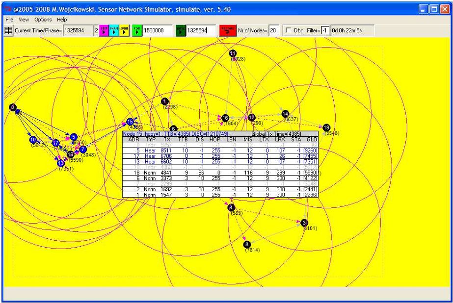
The main window of Sensor Network Simulator.
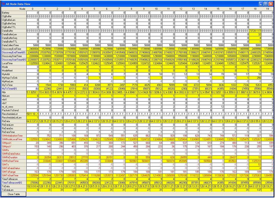
Editing the parameters in Sensor Network Simulator.
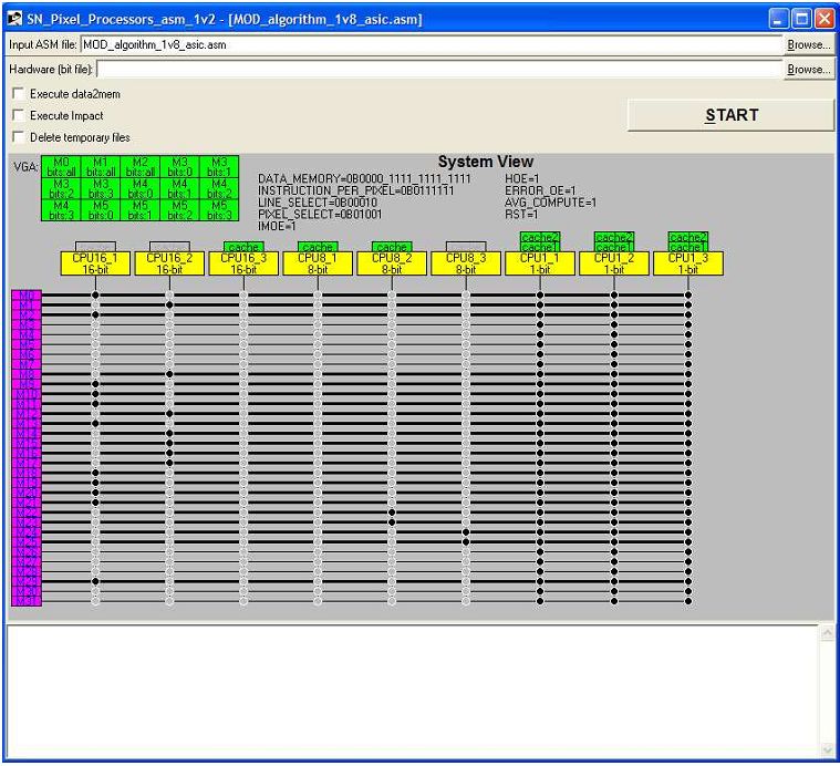
The assebler for the Pixel Processors.
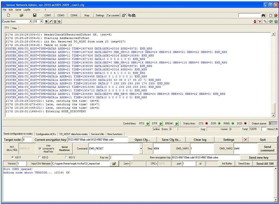
The main screen of Administration Software.
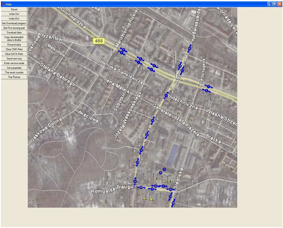
The map view in of Administration Software.
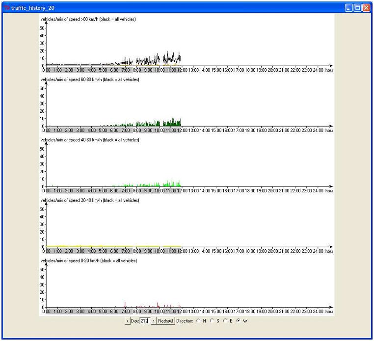
The traffic history view in Administration Software.
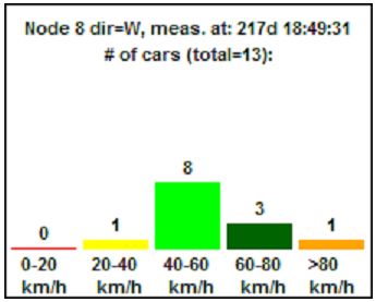
The histograms illustrating the traffic flow.
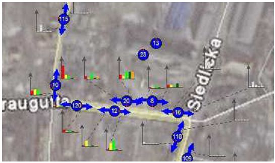
The mini histograms on the map view.
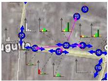
The illustration of radio connectivity on the map view.
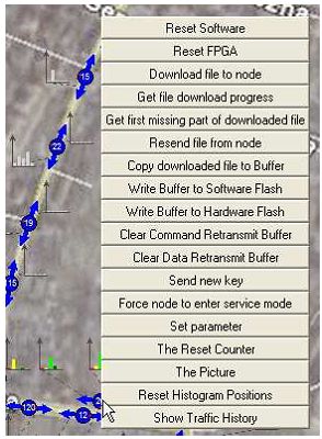
The context menu for administration of the nodes.
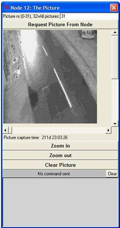
The picture downloaded from the node's camera.
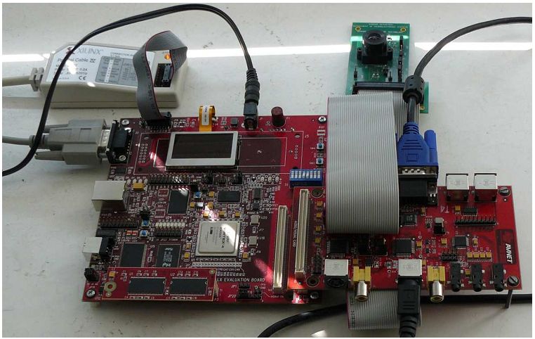
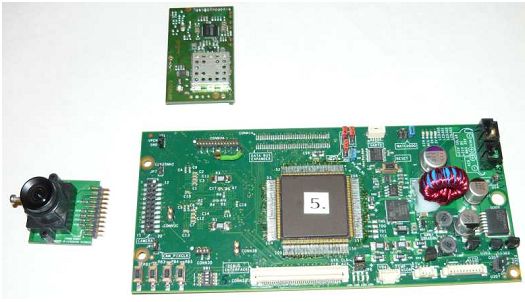
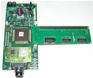
The first prototype using prototyping board with Xilinx Virtex-4 FPGA and added cutom camera PCB.

The PCB of the final FPGA prototype with Xilinx Virtex-4 FPGA.
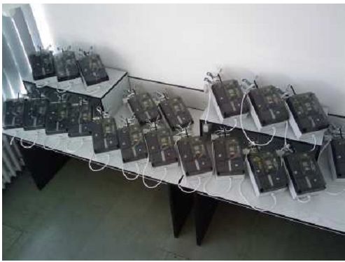
All FPGA prototype nodes ready for mounting on the street lamp poles.
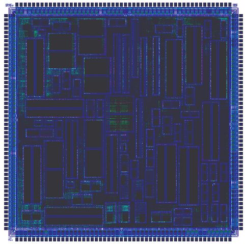
The layout of the designed ASIC. Process: CMOS UMC 130nm.
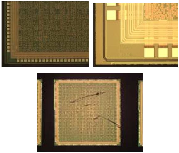
The picture of the manufactured die.
The picture of the naked dies.
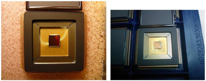
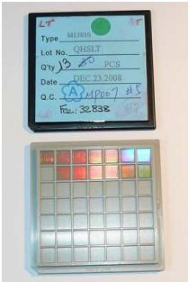
The packed ASIC.
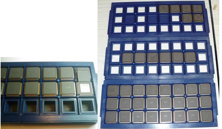
The picture of the manufactured ASICs.
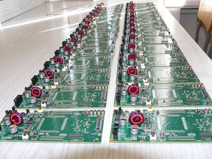
The PCBs of the ASIC prototype in production.
The view of disassembled ASIC prototype.
The ASIC prototype with attached service board for initial download of the bootloader software.
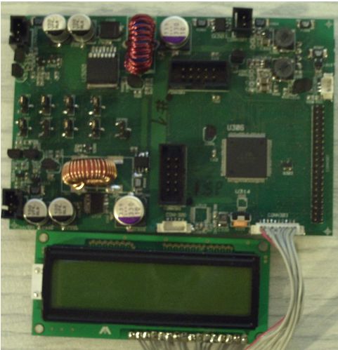
The power supply part of the ASIC prototype's PCB with attached LCD display for monitoring power supply.
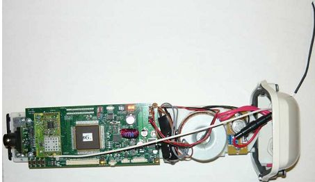
The ASIC prototype without housing.
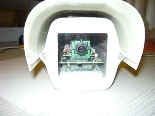
Front view of ready ASIC prototype.
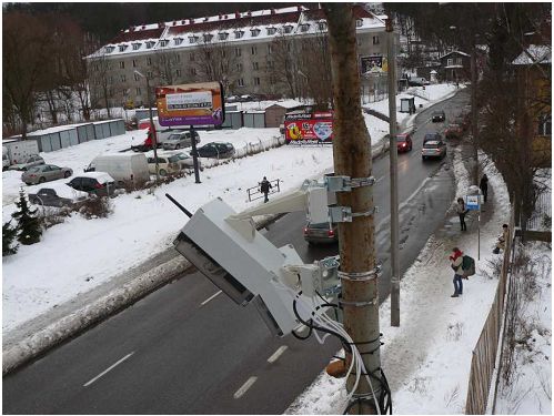
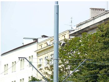
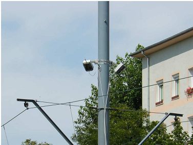
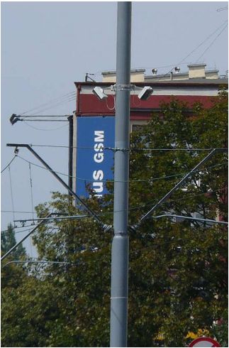
The nodes installed on the street.
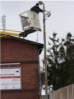
Installation of the nodes.
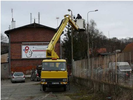
Installation of the nodes.
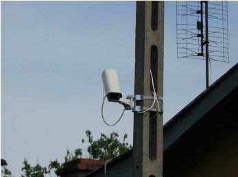
The node #109.
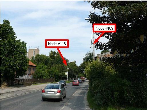
The nodes #109 and #118.
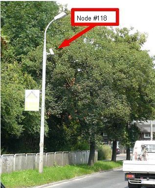
The node #118.
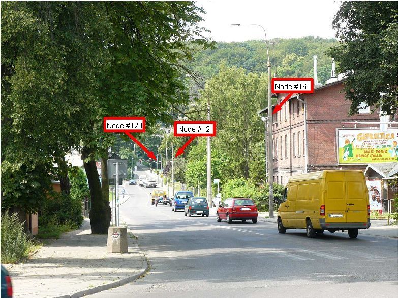
The nodes #12, #16 and #120.
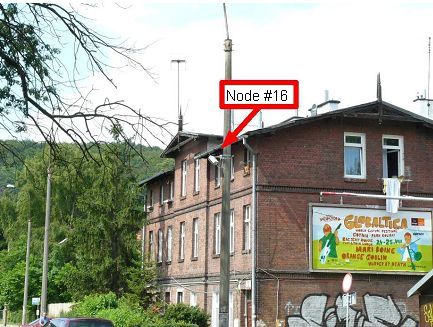
The node #16.
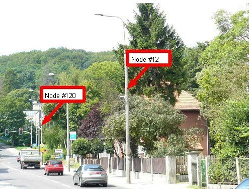
The nodes #12 and #120.
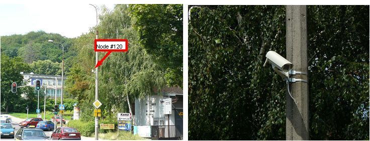
The node #120.
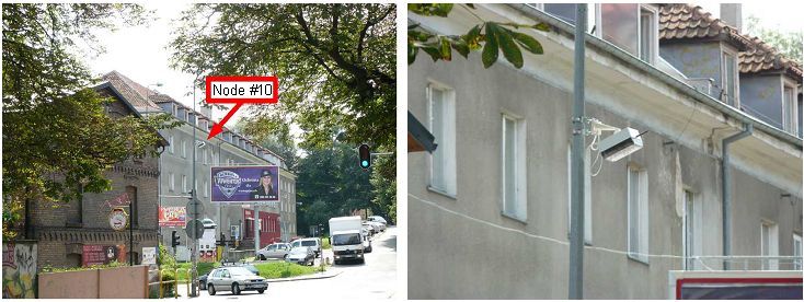
The node #10.
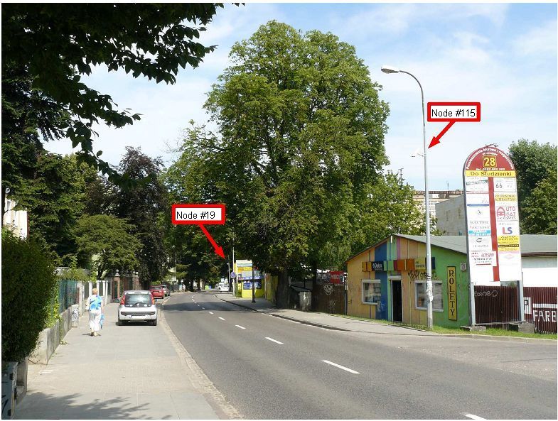
The nodes #19 and #115.
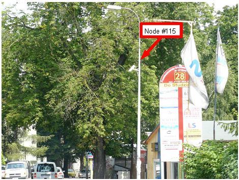
The node #115.
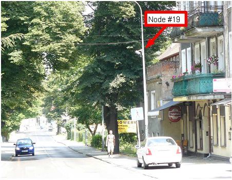
The node #19.
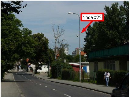
The node #22.
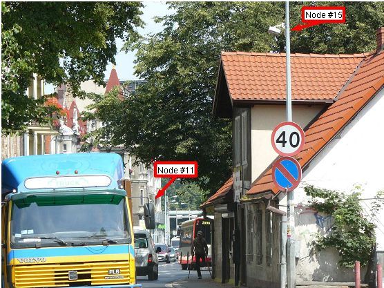
The nodes #11 and #15.
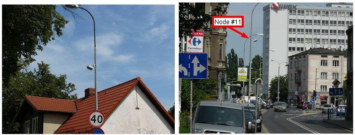
The nodes #11 and #15.
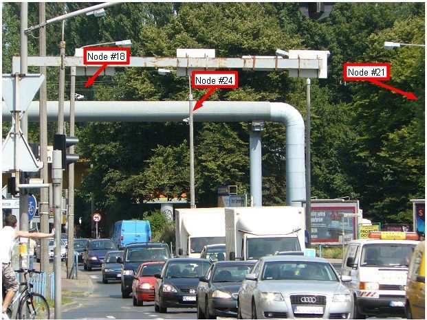
The nodes #18, #21 and #24.
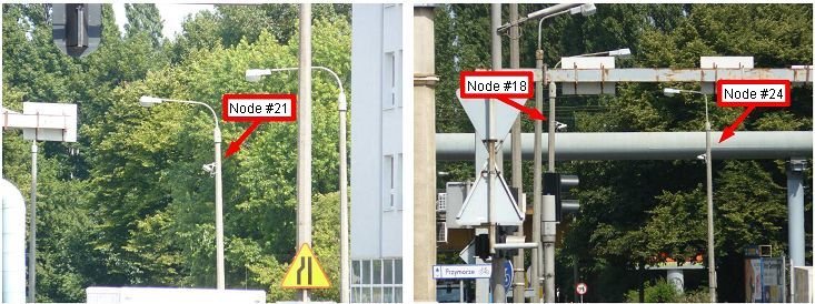
The nodes #18, #21 and #24.
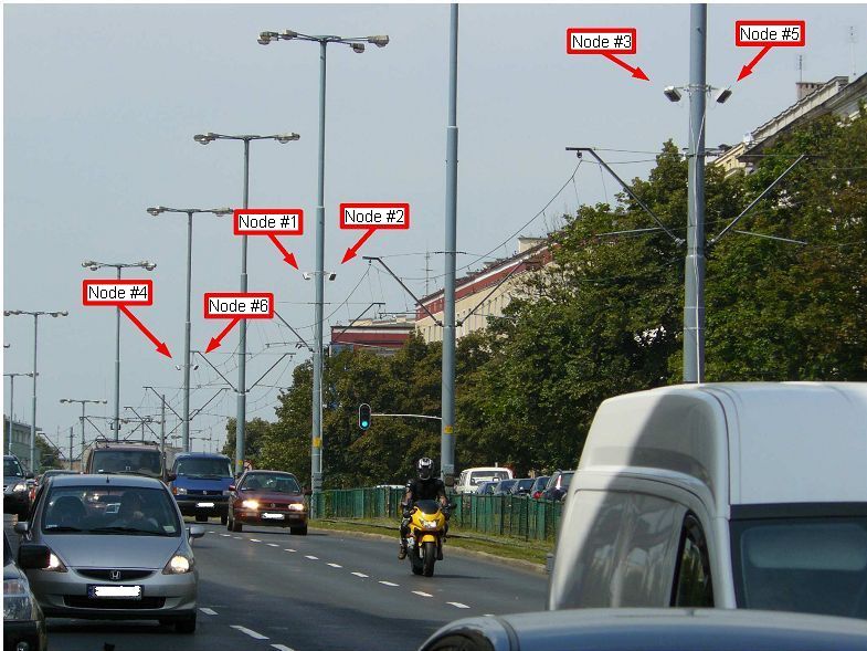
The nodes #1, #2, #3, #4, #5 and #6.
The nodes #1 and #2.
The nodes #3 and #5.
The nodes #4 and #6.
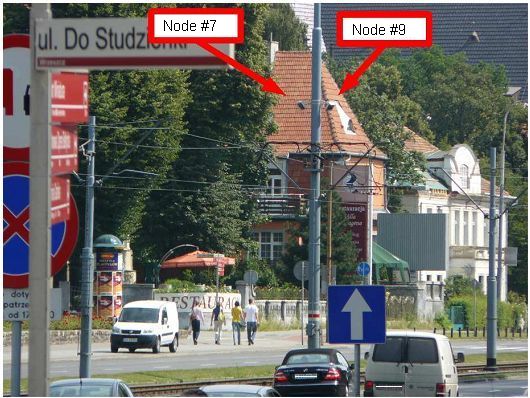
The nodes #7 and #9.