[PL]
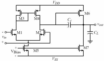
Two-stage operational amplifier
Calculations, simulation
tests, and layout design
Task:
· preparation for
lab - design of a standard two-stage operational amplifier,
·
simulation tests of designed operational amplifier,
·
layout design of the amplifier, extraction of the schematic from the
layout design and final verification of the amplifier parameters.
In
the exercise, design a standard two-stage operational amplifier, using the
procedure presented in lecture, for TSMC 0,35 μm (parameters, model) technology. The amplifier
parameters are given in the table, and the version assignments are listed in
the lista_aus file. NOTE, transistor sizes can be varied with a step of λ=0.2μm,
with a minimum transistor size of W/L=3λ/2λ. Assume the following
transistor parameters for the calculations: NMOS KP=94u VT0=0.55 GAMMA=0.55
LAMBDA=0.04; PMOS KP=33u VT0=-0.75 GAMMA=0.4 LAMBDA=0.06. In fact, the channel
length modulation factor LAMBDA depends on the channel length of the
transistor. To take this into account you can use the LAMBDA values provided in
the file lambda-f(L).txt.
After performing the calculations,
the basic parameters of the amplifier (Av, GB, PM, ICMR, Vout
range, SR, Pdiss) should be verified by simulation
(Spice MOS Level 1). Then, for the BSIM3 MOS model, optimize the amplifier so
that the set parameters are satisfied. All the amplifier parameters (Av, GB,
PM, ICMR, CMRR, PSRR, Vout range, SR, Rout Pdiss) should be verified by simulation and should be
stored in a table. Make the layout design of the amplifier using the MAGIC
program using transistor placement similar to exercise 2. From the layout
design, extract the amplifier schematic and perform final verification (and
possible optimization) of the amplifier parameters.
For the assignment, prepare a report
in doc, odt or pdf format according to the attached template. The report should
include a summary of the determined parameters in a table and the corresponding
graphs, calculations and conclusions. You should attach files for SPICE
simulator (cir) and layout projects (mag) to the
report. NOTE: Each simulation should be accompanied by the corresponding file
ready to run! Zipped reports with attached files should be sent only by e-mail,
in the subject write: Name_Sureme_index
number_AUSLAB_year_zad4_vx (vx - version number).
Specified
amplifier parameters:
|
Parametr |
Jednostka |
Opamp_v1 |
Opamp_v2 |
Opamp_v3 |
|
Av ≥ |
V/V |
20000 |
10000 |
10000 |
|
GB ≥ |
MHz |
5 |
10 |
13 |
|
ICMR ≥ |
V |
1.2-2.7 |
1.2-2.7 |
1.2-2.7 |
|
Voutrange ≥
|
V |
0.3-2.7 |
0.3-2.7 |
0.3-2.7 |
|
CL |
pF |
10 |
6 |
5 |
|
SR ≥ |
V/µs |
7 |
8 |
8 |
|
Vdd |
V |
3.0 |
3.0 |
3.0 |
Vss
|
V
|
0
|
0
|
0
|
|
Pdiss≤ |
mW |
0.6 |
1.0 |
1.0 |