

Integrated Sensor Network
Author: dr inż. M. Wójcikowski
TinyOS – General information
Fig. 1. Sensor network node IRIS XM2110.
Fig. 2. Sensor board MDA100
Fig. 3. Programming station
Fig. 4. Node in the docking station. When using USB power supply, the batteries must be removed.
1.1. Starting your work
1) Virtual machine disk image
Download virtual machine disk image from the network drive
- download virtual disk image Sensor_LAB_v5.vdi or locally: \\nas0\Public\lab_zss(approx. 7 GB, download time about 5 minutes) and save it on a local hard disk in arbitrary subfolder of the folder c:\Designs.
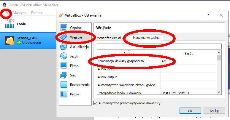
2) Setting of the Host key
Change the settings of the Host key in Virtual Box, if needed: Virtual Box Manager, menu File/Global settings, then Input and tab Virtual Machine: Host key combination.
In this way, a right keyWindows will be set as a host key. Using left Control could collide with other applications of virtual machine, such as Emacs editor.
3) Setting the virtual machine
The virtual machine should be already present in your system; if not, download also the file Sensor_LAB_v5.vbox and open it in Oracle VM Virtual Box using menu: Machine/Add.
In the virtual machine settings (Settings/Storage/Choose Virtual Hard Disk File...), set the path to the disk image file (Sensor_LAB_v5.vdi, according to step 1):
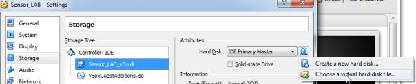
Fig. 5. The path to virtual machine's hard disk
If you have a problem with adding virtual disk (error message: Failed to open hard disk drive... already exists), you should remove old disks using menu File/Virtual Media Manager, then Release and Delete.
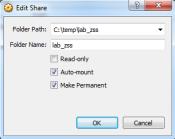
Additionally, you may set the shared folder, which will provide a way of exchanging the files between the virtual machine with Ubuntu and your computer. Set the folder in Settings/Shared Folders/Edit Shared Folder to match your working folder (check Auto mount, uncheck Read Only). After this, it will be possible to mount the shared folder in Ubuntu using the command mount (details are given at the end of this document).
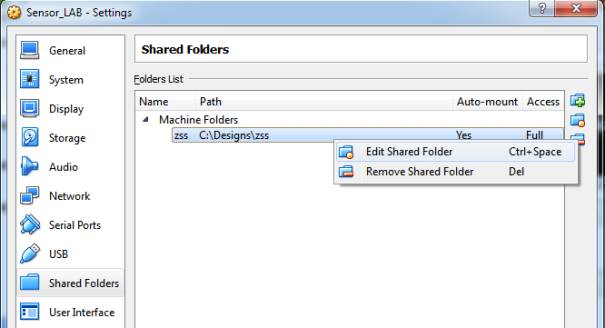
Fig. 6. Setting the shared folder
4) Start the virtual machine Oracle VirtualBox Sensor_LAB with Ubuntu (login: student, root's password is: student).
5) Start the terminal (Ctrl+Alt+T).
6) Check the TinyOS environment using the command: tos-check-env
The warning about newer version of some packets are acceptable, i.e.:
- java is in version 1.8 but TinyOS requires version 1.4 or 1.5 (to check the installed version of java use the command: java –version),
- graphviz is in version 2.38m and TinyOS requires version 1.10.
1.2. Configuration block
In folder tinyos-main/apps/Sense you can find a simple example of MicaMote application reading the values of the senor. Copy the folder tinyos-main/apps/Sense to your home directory for further work.
In TinyOS there are separate files containing the configuration and module.
- Configuration (the file name has the following structure: <nazwa>AppC.nc e.g. SensorAppC.nc) defines the connections of the module with other components.
- The file with the module (the file name has the form: <nazwa>C.nc e.g.: SensorC.nc) contains executable code of the application, here it is the application Sensor.
Each application requires the configuration file defining the top level of the project. In this example the top level is SensorAppC.nc defining the configuration of Sensor application. The configuration SensorAppC.nc contains the following code:
configuration SenseAppC {
}
implementation {
components SenseC, MainC, LedsC, new TimerMilliC(), new DemoSensorC() as Sensor;
SenseC.Boot -> MainC;
SenseC.Leds -> LedsC;
SenseC.Timer -> TimerMilliC;
SenseC.Read -> Sensor;
}
The configuration SensorAppC.nc contains an embedded module SenseC, which realizes the basic functionality of the application and it contains other modules (MainC, LedsC, TimerMilliC, DemoSensorC) with the connections, according to the figure below:
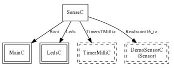
Fig. 7. Connection diagram in SensorAppC
Some components can exist only as singleton in the system – existence of their multiple copies would not make any sense, for example the components connected to the hardware devices (such as. LedsC). The components that can be embedded as multiple copies are denoted by the keyword new and they are connected with dashed lines on the diagrams (i.e. TimerMilliC in the figure above). The rectangles with single border denote the modules, the configurations are drawn using double line borders.
Changing the name of the instantiated module
The instantiated module can have its own new name. The name can be changed when the user wants to have more meaningful names or when multiple instances of the same modules are used (their names must be unique). In the example above, the component DemoSensorC has the name Sensor changes with keyword as. The names of the interfaces can also be changed in a similar way.
Interfaces
As described previously, configuration defines the connections between the modules. The connections are set between the modules' interfaces. The component can provide interfaces and also it can use them.
|
provides |
uses |
|
The interfaces are provided by the module for the application, which contains the instantiated module. The application can use the functionalities of the instantiated module only through the provided interfaces. |
The interfaces that the module uses. Those interfaces are necessary for the component to perform its operations. Those interfaces are used for communication with other modules instantiated in the configuration. |
Only compatible interfaces can be connected together. The interfaces are defined at the definition of the module. If the module has only one interface of certain type, its name can be omitted. In the above example, some interface names have been omitted, the formal notation should lookin the following way:
SenseC.Boot -> MainC.Boot;
SenseC.Leds -> LedsC.Leds;
SenseC.Timer -> TimerMilliC.Timer;
SenseC.Read -> Sensor.Read;
The modules instantiated in configuration SenseAppC.nc, e.g.: MainC, LedsC, TimerMilliC and Sensor provide the interfaces, that the module moduł SenseC uses. The module SenseC provides no interface, because this is a top level module for this application and it will not be used in other modules.
Module MainC
The module MainC is a system module, its interface Boot sindicates the moment of the end of the module's start up phase.
1.3. Module
The module can send commands to each interface, which it uses. According to the split-phase programming paradigm, the commands are sent to the interface without waiting for a confirmation. Thank to this, the operation of the main software is not blocked. An interface can present an event, which contains a feedback about the realization of the command. A module, which wants to send the command to the interface, must have the definitions of functions being executed when the interface's events occur.
The module SenseC has been defined in file SenseC.nc:
#include "Timer.h"
module SenseC {
uses {
interface Boot;
interface Leds;
interface Timer<TMilli>;
interface Read<uint16_t>;
}
}
implementation {
// pominięto część kodu.....
}
The module SenseC uses the following interfaces: Boot, Leds, Timer<TMilli> and Read<uint16_t>. Some interfaces can contain the type of data. TinyOS has the following types of data:
|
|
8 bits |
16 bits |
32 bits |
64 bits |
|
signed |
int8_t |
int16_t |
int32_t |
int64_t |
|
unsigned |
uint8_t |
uint16_t |
uint32_t |
uint64_t |
For the security, all data are local to the module, any exchange of information is done using the interfaces. The module can have its own local variables, containing the state of the module, i.e.:
uint8_t reading; /* 0 to NREADINGS */
and local functions:
void report_problem() { call Leds.led0Toggle(); }
Full implementation of the module SenseC is presented below:
#include "Timer.h"
module SenseC {
uses {
interface Boot;
interface Leds;
interface Timer<TMilli>;
interface Read<uint16_t>;
}
}
implementation {
// sampling frequency in binary milliseconds
#define SAMPLING_FREQUENCY 100
event void Boot.booted() {
call Timer.startPeriodic(SAMPLING_FREQUENCY);
}
event void Timer.fired() {
call Read.read();
}
event void Read.readDone(error_t result, uint16_t data) {
if (result == SUCCESS){
if (data & 0x0004)
call Leds.led2On();
else
call Leds.led2Off();
if (data & 0x0002)
call Leds.led1On();
else
call Leds.led1Off();
if (data & 0x0001)
call Leds.led0On();
else
call Leds.led0Off();
}
}
}
The functions called events are defined, which will be execued when the interfaces raise the events. When the event booted from the interface Boot arrive, the command startPeriodic should configure and start the Timer, to periodically generate the impulses:
event void Boot.booted() {
call Timer.startPeriodic(SAMPLING_FREQUENCY);
}
Upon reception of the event fromTimera, the read from interface Read must be executed:
event void Timer.fired() {
call Read.read();
}
Having the result, it should be displayed on LEDs. As there are only 3 LEDs, only the LSB bits will be presented:
event void Read.readDone(error_t result, uint16_t data) {
if (result == SUCCESS){
if (data & 0x0004)
call Leds.led2On();
else
call Leds.led2Off();
if (data & 0x0002)
call Leds.led1On();
else
call Leds.led1Off();
if (data & 0x0001)
call Leds.led0On();
else
call Leds.led0Off();
}
}
}
1.4. Compilation
To compile the application, the following command must be run (in apps folder, e.g. Sense):
make iris
Successful compilation should give the following results:
mkdir -p build/iris
compiling SenseAppC to a iris binary
ncc -o build/iris/main.exe -Os -fnesc-separator=__ -Wall -Wshadow -Wnesc-all -target=iris -fnesc-cfile=build/iris/app.c -board=micasb -DDEFINED_TOS_AM_GROUP=0x22 --param max-inline-insns-single=100000 -DIDENT_APPNAME=\"SenseAppC\" -DIDENT_USERNAME=\"student\" -DIDENT_HOSTNAME=\"student-Virtual\" -DIDENT_USERHASH=0xf0999aa1L -DIDENT_TIMESTAMP=0x5501abd7L -DIDENT_UIDHASH=0x692fd64bL -fnesc-dump=wiring -fnesc-dump='interfaces(!abstract())' -fnesc-dump='referenced(interfacedefs, components)' -fnesc-dumpfile=build/iris/wiring-check.xml SenseAppC.nc -lm
compiled SenseAppC to build/iris/main.exe
3126 bytes in ROM
47 bytes in RAM
avr-objcopy --output-target=srec build/iris/main.exe build/iris/main.srec
avr-objcopy --output-target=ihex build/iris/main.exe build/iris/main.ihex
writing TOS image
1.5. Programming the node
After successful compilation, the node can be programmed. Remove the batteries and install the node in the base station, together with the sensor board.
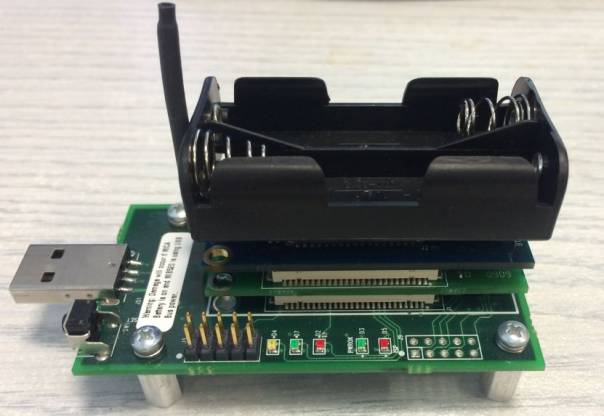
Fig. 8. Picture of the node with the sensor board installed in the base station
WARNING: Installation of the node containing the batteries to the base station connected to USB will damage the node!
1) Connect the assembled base station with the node and sensor board to computer's USB port.
2) Activate USB port Crossbow MIB520CA in virtual machine (right-click on lower right corner of VirtualBox window on icon ![]() ):
):
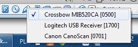
Rys. 9.
3) Check the nubmer of ports:
dmesg | grep ttyUSB
dmesg = display the messages from starting the system
and
ls /sys/class/tty
The docking station provides two ports of consecutive numbers. The lower number denotes the port used for programming; the upper port is used for communication with the node. Typically, you will have:
/dev/ttyUSB0 - for programming;
/dev/ttyUSB1 – for communication.
4) Use the command
make iris install,<node_no> mib520,/dev/ttyUSB<USB_port_no>
i.e.:
make iris install,0 mib520,/dev/ttyUSB0
to program the node. Use the number of your computer (1-15) as ,<node_no> to avoid the conflicts with other students. Replace <USB_port_no> with the lower USB port number, typically it will be 0. The results of correct programming look like:
avrdude: 14384 bytes of flash written
avrdude: verifying flash memory against build/iris/main.srec.out-101:
avrdude: load data flash data from input file build/iris/main.srec.out-101:
avrdude: input file build/iris/main.srec.out-101 auto detected as Motorola S-Record
avrdude: input file build/iris/main.srec.out-101 contains 14384 bytes
avrdude: reading on-chip flash data:
Reading | ################################################## | 100% 2.42s
avrdude: verifying ...
avrdude: 14384 bytes of flash verified
avrdude: safemode: Fuses OK
avrdude done. Thank you.
rm -f build/iris/main.exe.out-101 build/iris/main.srec.out-101
1.6. Documentation of the project
The command:
make iris docs
generates the documentation of our project.
In web browser of Ubuntu system (e.g. Firefox) enter the file name index.html, as:
file:///home/student/Sense/doc/nesdoc/iris/index.html
Read the documentation of the implementation, scroll down the the right side of the window to see the components and select SenseAppC.
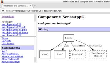
Fig. 10. Documentation of the project
1.7. Printing the messages with printf:
The component in the node can send text messages to the computer through the base station can. Such messages are useful for debugging the system. The presented procedure will help you to implement the possibility to use printf in your code:
1) Add the path to printf module in the project's Makefile:
CFLAGS += -I$(TOSDIR)/lib/printf
2) Add the commands to the configuration *AppC.nc:
#define NEW_PRINTF_SEMANTICS
#include "printf.h"
...
and attach the following components:
components PrintfC;
components SerialStartC;
3) In file (*C.nc) and the header:
#include "printf.h"
From now you can use the printf function in your events:
printf("Hi I am writing to you from my TinyOS application!!\n");
printf("Here is a uint8: %u\n", dummyVar1);
printf("Here is a uint16: %u\n", dummyVar2);
printf("Here is a uint32: %ld\n", dummyVar3);
printfflush();
At the end it is convenient to add command printfflush() – the message will be printed immediately.
To capture the messages generated by the node, run the application:
java net.tinyos.tools.PrintfClient -comm serial@/dev/ttyUSB<no>:iris
typically:
java net.tinyos.tools.PrintfClient -comm serial@/dev/ttyUSB1:iris
Remember to enter the correct USB port number <no> used for communication (the upper port).
Additional information
http://tinyos.stanford.edu/tinyos-wiki/index.php/TinyOS_Documentation_Wiki
If you have problems with scaling the window of VirtualBox, install the following package in Ubuntu:
sudo apt-get install virtualbox-guest-dkms
To exchange data between the PC and virtual machine, define a shared folder in virtual machine (Oracle Virtual Box / Devices/Shared Folder Settings...).
In Ubuntu map the folder:
sudo mount -t vboxsf -o uid=$UID,gid=$(id -g) lab_zss /mnt
Now the folder will be mounted in Ubuntu at /mnt.