

Parity generator (Remote Lab)
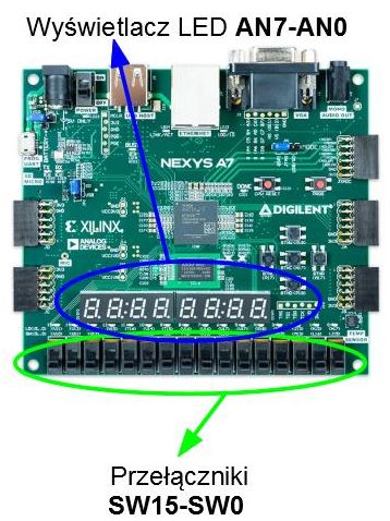
Task: Design a circuit generating parity bit of 8-bit word. The 8-bit word has to be set using virtual switches SW7-SW0 on the prototype board. Parity has to be shown on LED display: E - even number of "ones" in 8-bit input word, O - odd number of "ones" in 8-bit input word.
Virtual buttons are controlled by putty (connection parameters: typically it is port COM3; speed: 9600). In case of connection problems - see the manual.
Tasks:
- describe the circuit using HDL language,
- write the testbench and perform functional simulation,
- prepare constraints in XDC format,
- implement the circuit by programming the prototype board.
The prototype board contains eight seven-segment LED displays with common anode, designed to drive segments using multiplexing. The result should be displayed on any digit. All the segments of all 8 LED displays are connected together, i.e. all segments A are connected together, all segments B are connected together, etc. Common anodes are for activating specific digit. Segments (A-G) are driven with active low signal, also digits AN7-AN0 are active low. For example, to blank digits 0-2, signals AN0-AN2 should be driven with logic '1'. Additionally, to display letter "A" on display 3, the following signals have to be asserted: AN3='0' and A='0', B='0', C='0', D='1', E='0', F='0', G='0', DP='1'.
More details and schematic diagrams are in Nexys A7™ FPGA Board Reference Manual, on pages 22-24.
Constraints file in XDC format for this exercise, Digilent Nexys A7 board, FPGA: Artix-7 XC7A100T-1CSG324C (package: CSG324, speed grade:-1):
#########################################################################################
# Virtual DIP SW:
set_property -dict { PACKAGE_PIN H14 IOSTANDARD LVCMOS33 } [get_ports sw_i[0] ]
set_property -dict { PACKAGE_PIN G16 IOSTANDARD LVCMOS33 } [get_ports sw_i[1] ]
set_property -dict { PACKAGE_PIN F16 IOSTANDARD LVCMOS33 } [get_ports sw_i[2] ]
set_property -dict { PACKAGE_PIN D14 IOSTANDARD LVCMOS33 } [get_ports sw_i[3] ]
set_property -dict { PACKAGE_PIN G18 IOSTANDARD LVCMOS33 } [get_ports sw_i[4] ]
set_property -dict { PACKAGE_PIN F18 IOSTANDARD LVCMOS33 } [get_ports sw_i[5] ]
set_property -dict { PACKAGE_PIN E17 IOSTANDARD LVCMOS33 } [get_ports sw_i[6] ]
set_property -dict { PACKAGE_PIN D17 IOSTANDARD LVCMOS33 } [get_ports sw_i[7] ]
#########################################################################################
#7-SEG LED:
set_property -dict { PACKAGE_PIN J17 IOSTANDARD LVCMOS33 } [get_ports an_o[0]]
set_property -dict { PACKAGE_PIN J18 IOSTANDARD LVCMOS33 } [get_ports an_o[1]]
set_property -dict { PACKAGE_PIN T9 IOSTANDARD LVCMOS33 } [get_ports an_o[2]]
set_property -dict { PACKAGE_PIN J14 IOSTANDARD LVCMOS33 } [get_ports an_o[3]]
set_property -dict { PACKAGE_PIN P14 IOSTANDARD LVCMOS33 } [get_ports an_o[4]]
set_property -dict { PACKAGE_PIN T14 IOSTANDARD LVCMOS33 } [get_ports an_o[5]]
set_property -dict { PACKAGE_PIN K2 IOSTANDARD LVCMOS33 } [get_ports an_o[6]]
set_property -dict { PACKAGE_PIN U13 IOSTANDARD LVCMOS33 } [get_ports an_o[7]]
set_property -dict { PACKAGE_PIN T10 IOSTANDARD LVCMOS33 } [get_ports seg_o[7]]
set_property -dict { PACKAGE_PIN R10 IOSTANDARD LVCMOS33 } [get_ports seg_o[6]]
set_property -dict { PACKAGE_PIN K16 IOSTANDARD LVCMOS33 } [get_ports seg_o[5]]
set_property -dict { PACKAGE_PIN K13 IOSTANDARD LVCMOS33 } [get_ports seg_o[4]]
set_property -dict { PACKAGE_PIN P15 IOSTANDARD LVCMOS33 } [get_ports seg_o[3]]
set_property -dict { PACKAGE_PIN T11 IOSTANDARD LVCMOS33 } [get_ports seg_o[2]]
set_property -dict { PACKAGE_PIN L18 IOSTANDARD LVCMOS33 } [get_ports seg_o[1]]
set_property -dict { PACKAGE_PIN H15 IOSTANDARD LVCMOS33 } [get_ports seg_o[0]]
#########################################################################################