

Lab 2: Writing basic software application
This text is based on teaching materials from Xilinx (www.xilinx.com).
Contents
Step 1: Exporting the hardware to SDK
Step 2: Creating new application in Xilinx SDK
Step 3: Examine the files and projects in your system
Step 5: Write application to use timer
Results required to complete the exercise
Introduction
The purpose of this lab exercise is write end execute the software using Xilinx SDK on the hardware design created in Lab 1. In this lab, you will and create and run simple “hello world” software. You will also configure and use the hardware timer to measure the time. After completing this lab, you will be able to create a simple software and execute it on the created hardware.
Setup
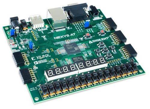
For this lab, you will need a Xilinx Nexys A7 FPGA Board and a USB cable. Connect the USB cable to the PC and the Nexys A7 Board to connector PROG/UART. With this cable, the programming of the FPGA will be done, as well as serial communication between the board and PC.
Step 1: Exporting the hardware to SDK
Having your hardware ready, you need to create software. This is done in another tool called Xilinx SDK. First you have to export your hardware from Vivado to Xilinx SDK.
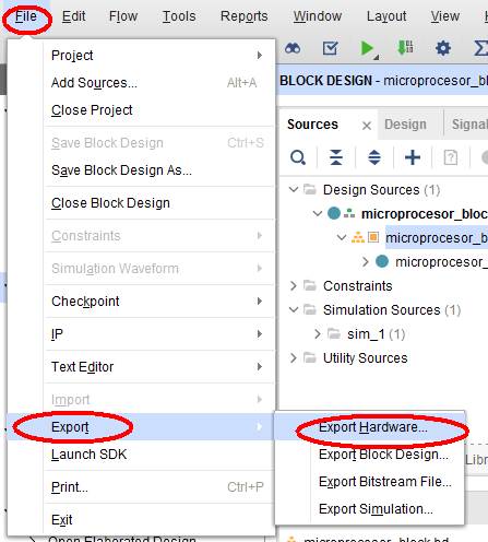
1. In Vivado you will export your design and launch Xilinx SDK with the following commands:
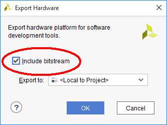
Do not forget to select the include the bitstream in the exported platform:
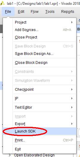
2. Finally you launch Xilinx SDK to start creating the software:
Step 2: Creating new application in Xilinx SDK
Xilinx SDK opens with already created hardware platform imported from Vivado. Hardware platform contains information about the hardware resources needed by the software, such as the number and types of microprocessors, the list of peripheral devices and the addresses of their registers. Whenever you change the hardware in Vivado, the hardware platform should be updated.
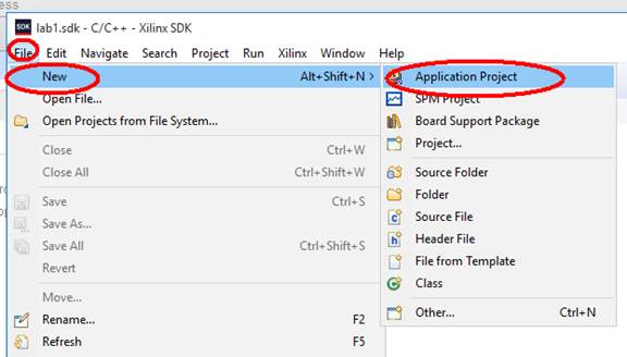
1. Create new application project from menu File/New/Application project:
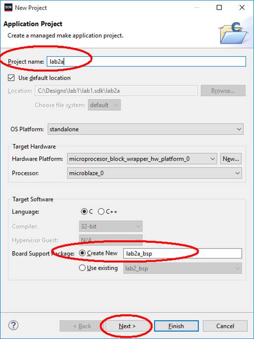
Enter the name of your application. You should also let the software to create new Board Support Package (BSP) for this platform. BSP is a set of software which is dedicated for a given hardware platform and is used by application (it is the software that mediates between your application and the hardware). BSP contains the drivers for hardware devices, their addresses and parameters which can be easily used by applications:
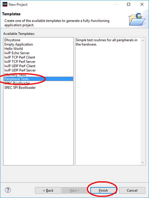
Then you ask for creation of template project containing tests for the peripheral devices available in the system and click Finish:
Step 3: Examine the files and projects in your system
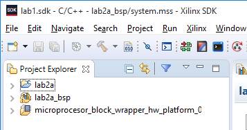
Your environment in SDK should now contain three projects:
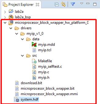
- Hardware platform ![]()
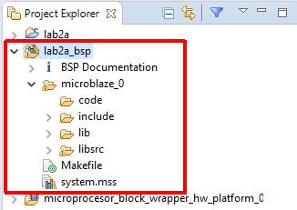
- Board Support Package ![]()
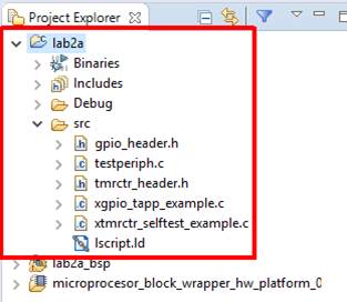
- User C application ![]()
1. First examine the files in the hardware platform, open *.hdf file and see what is inside. If there is a custom IP block in your hardware (you will add it later), you will also see the drivers for it.
2. Then examine BSP project. In system.mss you will find software settings for your application:
· the operating system used (or standalone);
· which device will be used for stdin and stdout (for standalone);
· drivers for hardware blocks;
· compiler flags and settings.
In microblaze_0/include there are all include files.
First take a look at xil_types.h – there are defined types of variables you should use in your application: for example u32, u8.
Another important file is xparameters.h which contains macros with the addresses and parameters of your hardware. When writing your software, you should not use the numerical addresses but macros from this file. When the hardware changes, the addresses can also change, but all the changes will be automatically included in xparameters.h. Therefore, if you use the macros from xparameters.h, you do not need to track the changes in hardware.
In microblaze_0/libsrc there are many folders with the drivers – if you want to use a hardware peripheral block in your software, you need to look at those files to see which driver functions are available and how to use them.
3. Finally take a look at application project. In src subdirectory there are all *.c and *.h files that make you your application:
Look for the main() function in the *.c files in src directory. There can be only one main() in the project. However, in our example you will find main() in testperiph.c and xgpio_tapp_example.c. The latter is excuded by the preprocessor, because it is surrounded by the preprocessor directive #ifndef TESTAPP_GEN and TESTAPP_GEN is not defined. Therefore, in our example, the main() function is in testperiph.c. Please take a look at it, so you will know what happens when you run the software.
Step 4: Run test application
Before you start running the applications, you need to “produce” the hardware. The bitstream file containing the configuration of your hardware has been generated in Vivado during Lab 1. Now you have to send this file to FPGA to program it.
If you have problems with programming and you cannot manually reset the board (remote lab), check this document: Remote reset by JTAG.
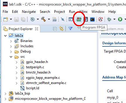
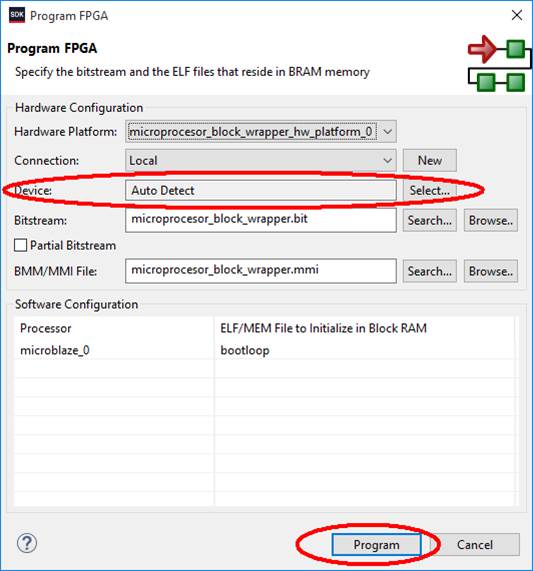
1. Click on the following button to send bitstream file by the JTAG programmer, which is connected to the PC by USB cable:
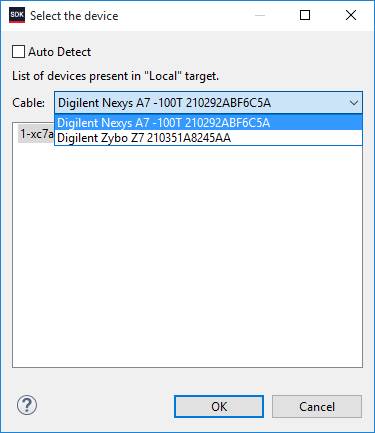
If you have more than one board connected to your PC, it could be necessary to select which board to program:
In the next window you can decide not to use auto detection, but specifically decide which device will be programmed:
More information you will find here: Working with multiple FPGAs connected to the PC
After several seconds you should see the programming progress:
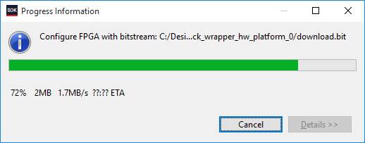
and finally “configuration complete” message. Now our hardware is “produced” inside FPGA, but it has no software, so you will not see any results on the FPGA board yet.
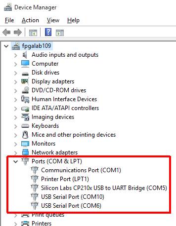
2. Now you need to determine the serial port number of your FPGA board connected by USB. In Windows open the Device Manager:
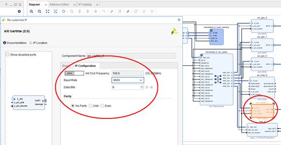
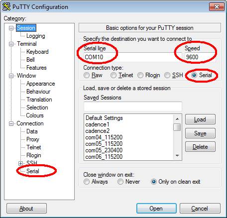
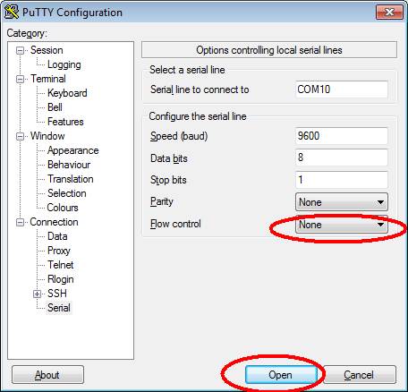
3. Run serial port terminal, for example putty in Windows and configure it for serial configuration. You need to specify the serial port number and the serial transmission parameters such as speed, number of data or parity bits and handshaking method. Those settings must be the same as used by your hardware block – you can check them in the uartlite block parameters in Vivado.
 For example, putty settings are presented below, assuming COM10:
Now you will see the serial port terminal window connected to your microelectronic system on your PC. So it is the time to run the software.
4. Right-click on your application project and select Run As/Launch on hardware:
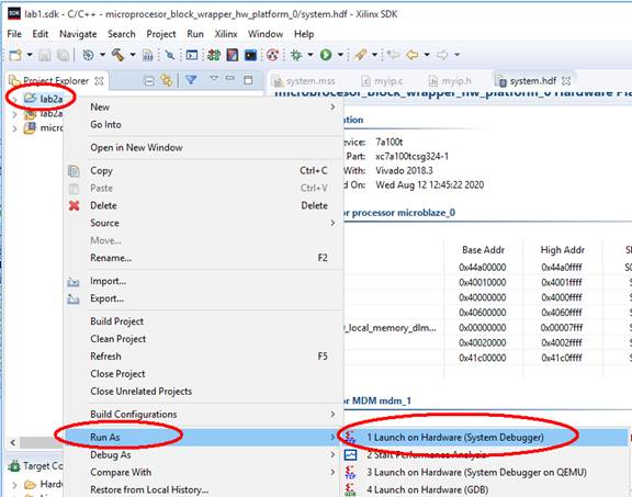
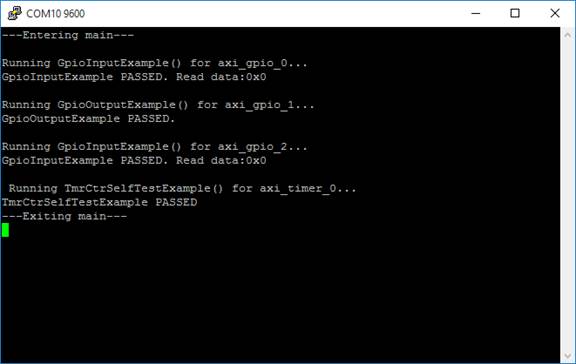
The SDK will use buit-in debugger to send the application code to the on-chip memory and execute it. You should see the application output:
Step 5: Write application to use timer
Now you will modify the template application from the previous step to use the timer to measure the delay. The timer should be configured to count down from the initial value to zero. Your task is to write the function realizing the delay which will use the timer the software should be polling if the timer has reached zero.
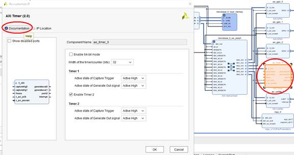
1. First you should read the documentation of the hardware block of the timer to know what are the capabilities of this device and what registers need to be set:
Then you need to read the inline documentation of the drivers available in BSP. In this lab you should use normal (not low-level) drivers, so open the file microblaze_0/libsrc/tmrctr_vXX/src/xtrmctr.c in your BSP project. There you will find the functions which should be used in this lab:
· XTmrCtr_Initialize() – for initializing XTmrCtr object. Device ID needed by this function you will find in xparameters.h file in BSP. You should check the return value of this function!
· XTmrCtr_SetOptions() – for setting timer options. You should set the timer to count down and you should enable the interrupt output (use flags XTC_DOWN_COUNT_OPTION and XTC_INT_MODE_OPTION from microblaze_0/libsrc/tmrctr_vXX/src/xtrmctr.c in your BSP project).
· XTmrCtr_SetResetValue() – for setting the starting value for the counter.
· XTmrCtr_Start() – for starting the timer.
· XTmrCtr_IsExpired() - for checking if timer has reached zero.
· XTmrCtr_Reset() - for reloading and resetting the timer.
2. Create the function:
void timerDelay(int delay_ms)
which will be using the hardware timer to measure the time and use it in main() to present the operation, for example:
print("Testing 5 second delay:\n\r");
timerDelay(5000);
print("Finished!\n\r");
Conclusions
You have created the C software for your hardware. Hardware has been designed in Vivado, software has been created in Xilinx SDK with the hardware platform data imported into Xilinx SDK from Vivado. You should now know how to look for the configuration of your hardware and the documentation of software drivers.
In future labs in this course, you will learn how to add user cores, simulate the design, debug the software, and verify the complete design functionality by using a hardware board.
Results required to complete the exercise
· Answer the questions in the test: https://docs.google.com/forms/d/e/1FAIpQLSdydplL2475EHe_q2DhDt2K4m_nax8zzVEIow6v91ZoXtoCwQ/viewform?usp=sf_link
· Present the source codes and the operation of the timer on serial port console to the teacher.
Change history
Adaptation to version Vivado 2018.3: M. Wójcikowski (08/2020).