

Lab 4: Advanced Software Writing
This text is based on teaching materials from Xilinx (www.xilinx.com).
Contents
Step 1: Adding interrupt controller to the microprocessor system
Results required to complete the exercise
Introduction
This lab guides you through the process of writing a software application that utilizes timer and interrupts. Vivado will be used to add interrupt controller hardware block to the microprocessor system and Xilinx SDK will be used to write the C software for using timer, interrupt controller and 7-segment LED block.
Setup
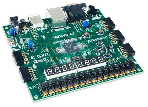
For this lab, you will need a Xilinx Nexys A7 FPGA Board and a USB cable. Connect the USB cable to the PC and the Nexys A7 Board to connector PROG/UART. With this cable, the programming of the FPGA will be done, as well as serial communication between the board and PC.
Step 1: Adding interrupt controller to the microprocessor system
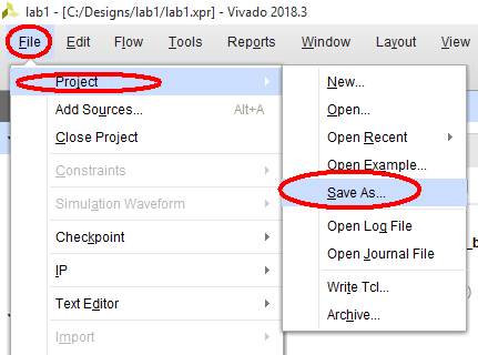
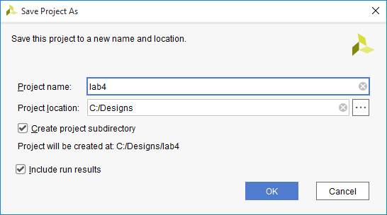
1. Open the project created in the lab3 and save it as a new project, for example lab4.
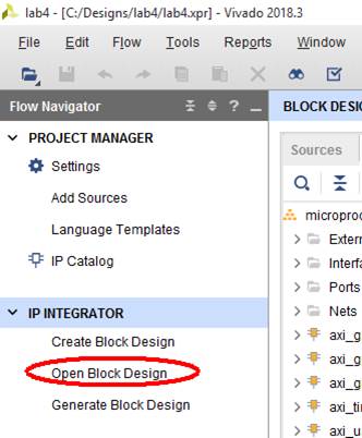
2. Click Open Block Design to edit the block diagram of the system:
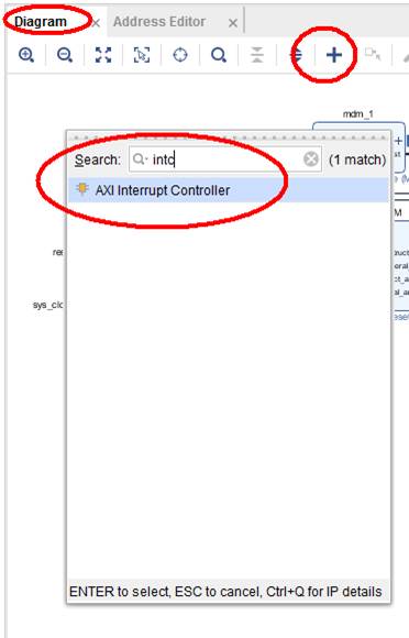
3. And add AXI Interrupt Controller from IP catalog using "+" in block diagram editor:
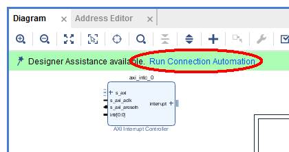
4. Run Connection Automation wizard with the default settings:
Now the interrupt controller (intc) block is connected to AXI bus, but the interrupts inputs and output are not connected (shown in red ellipses in the picture below). You need to connect them manually (shown as green lines in the picture below).
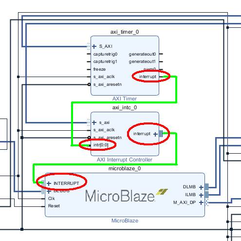
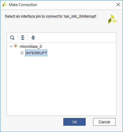
5. Connect the interrupt output of intc to the MicroBlaze:
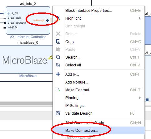
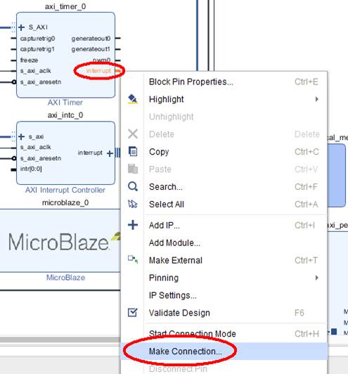
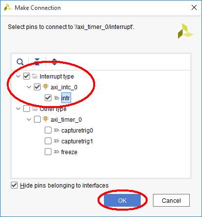
6. Connect the interrupt output of the timer to the intr input of the interrupt controller. The interrupt controller has 32 input lines, but we will use only one interrupt input in this example. The connection, polarity and interrupt input type (level or edge) is automatically set by Vivado.
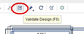
7. When you finish all the changes in block diagram, it is a good idea to perform validation:
8. Generate bitstream.
9. Export hardware design to SDK, including the bitstream.
10. Launch SDK.
Step 2: Writing the software which will be using interrupts to update 7-segment LED display with new counter’s values
Your task is to write the software, which will use interrupts generated by the timer every one second to increase the value displayed on the 7-segment LED display.
The hardware is ready: timer’s interrupts are connected to the interrupt controller and the interrupt controller is connected to the MicroBlaze’s interrupt input. Now you must instruct the MicroBlaze what to do when the interrupt arrives. When the interrupt is detected at the processor, it should call the interrupt service routine (ISR) of interrupt controller. Then this ISR will check all inputs of the interrupt controller and it will call dedicated ISRs for each active interrupt, in our case there is only one input used and connected to the timer, so the timer’s ISR should be started. The timer’s ISR should call the user function which should include all the commands that user wants to be executed at each interrupt from the timer. The timer’s ISR, except from calling user function, it will also acknowledge the interrupt at the timer, so the user do not need to worry about this. In a similar way, the ISR from interrupt controller also acknowledges the serviced interrupts at the controller.
1. In Xilinx SDK create new application project (Hello world template) together with Board Support Platform (BSP), as you did earlier.
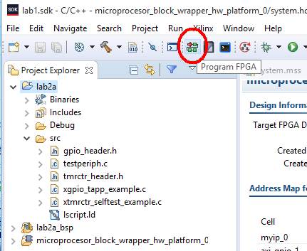
2. Click on the programming button to program the new hardware with intc to the FPGA:
If you have more than one prototype board connected to your PC, you should follow the procedure given here: Working with multiple FPGAs connected to the PC.
3. To configure and initialize the timer, use the same functions as you did in lab2, only add the option of auto-reload (XTC_AUTO_RELOAD_OPTION) of the timer to the function XTmrCtr_SetOptions(). The documentation of the drivers’ functions you can find in the folder microblaze_0/libsrc/tmrctr_vXX/src of your BSP. Please note, that some driver functions (high-level) use the reference to the timer’s instance, while some other (low-level) use the base address of the timer.
4. Then you should test the timer, if it is counting and generating signals every 1 second. For this purpose you can use the following routine:
while (1) {
// our timer block has two timers, we will use timer0 here:
int TmrCtrNumber =0;
// wait for the timer to reach the limit:
while (!XTmrCtr_IsExpired(&TimerInstance,TmrCtrNumber)) {}
// read the control and status register of the timer:
u32 ControlStatusReg = XTmrCtr_ReadReg(TimerInstance.BaseAddress, TmrCtrNumber, XTC_TCSR_OFFSET);
// clear the flag, so the timer can signal the next overflow:
XTmrCtr_WriteReg(TimerInstance.BaseAddress, TmrCtrNumber, XTC_TCSR_OFFSET, ControlStatusReg | XTC_CSR_INT_OCCURED_MASK);
// print the character so you can see how often the timer rolls over:
print("*");
}
If you see the star (*) printed at every second on serial port, you can comment out the above listed code, it will not be used any more. You can be sure, that the timer is working and it is generating interrupts every one second.
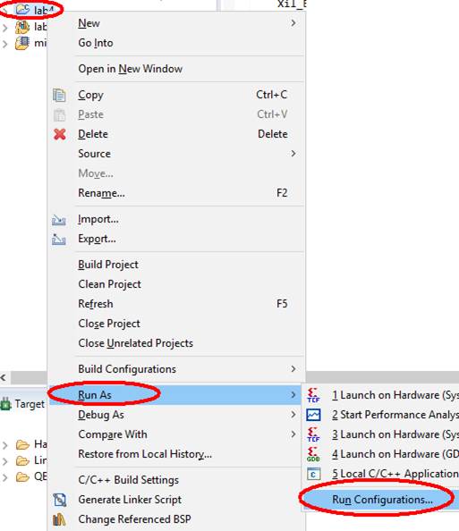
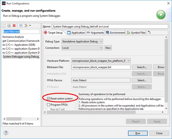
5. As you will be using interrupt controller, you should configure the Run Configuration, so the whole system is reset (including the interrupt controller). As default, only the processor is reset, not the peripheral blocks. This default setting can cause the problem, if you have started interrupt controller and timer in your previous software tests or runs. Then when new software starts, the timer and interrupts controller generates interrupts just at the beginning of the new instance of the software. Therefore you need to reset WHOLE system, not only microprocessor at each run of the software. This can be done by changing Run Configuration:
and check Reset entire system setting:
If you have more than one prototype board connected to your PC, you should follow the procedure given here: Working with multiple FPGAs connected to the PC.
If you have problems with programming and you cannot manually reset the board (remote lab), check this document: Remote reset by JTAG.
6. Write your interrupt service routine (C function), where you will:
· Increment the global counter
· Send the value of this global counter to the 7-segment LED display.
Your service routine will be registered at the timer’s ISR using the function XTmrCtr_SetHandler(), so your function should have the parameters and return value the same as required by XTmrCtr_SetHandler() - defined by the type XTmrCtr_Handler, see the source code at BSP.
7. Register your ISR at the timer’s ISR using the function XTmrCtr_SetHandler().
8. Configure interrupt controller. You should use the following functions:
· XIntc_Initialize() – to initialize intc software object;
· XIntc_SelfTest() – to test if the hardware of intc exists and it is working;
· XIntc_Connect() – to register the timer ISR XTmrCtr_InterruptHandler() at the interrupt service routine of the interrupt controller;
· XIntc_Start() – to start the interrupt controller; use real mode (XIN_REAL_MODE), unless you want to test ISR from the software (optional);
· XIntc_Enable() – to enable the interrupt input of the controller which is associated with the timer;
9. Configure the interrupts at the MicroBlaze. You should use the following functions:
· Xil_ExceptionInit() – to setup the exception table (in fact this is not used in MicroBlaze);
· Xil_ExceptionRegisterHandler() – to register this intc ISR handler XIntc_DeviceInterruptHandler () at the MicroBlaze;
· Xil_ExceptionEnable() – to enable interrupts at the MicroBlaze.
10. Write the rest of your main() function. As most of the functionality is done in interrupt service routine, the rest of your main() function can look like this:
xil_printf("Starting counting in ISR:\n\r");
while (1) {}
Run the code and present it as the result of this lab.
Conclusions
You have added the interrupt controller to your system, and connected it to timer and to processor. You also wrote your own ISR, and registered it the timer’s ISR. You also registered timer’s ISR at the interrupt controller ISR. Finally you registered interrupt controller ISR at MicroBlaze. You also configured the timer, interrupt controller and MicroBlaze to generate or accept and service the interrupts.
Results required to complete the exercise
· Answer the questions in the test: https://docs.google.com/forms/d/e/1FAIpQLSem7ZEFfs0FvIPQFI24g7CnpWRH0UK9ixRpYbjcH_p57Z8EVw/viewform?usp=sf_link
· Present the soruce codes and the operation of the timer with the interrupts on the LED display on Nexys board to the teacher.
Change history
Adaptation to version Vivado 2018.3: M. Wójcikowski (08/2020).